The following is excerpted from “The Essential Woodworker,” by Robert Wearing. In our opinion, “The Essential Woodworker” is one of the best books on hand-tool usage written in the post-Charles Hayward era. Wearing was classically trained in England as a woodworker and embraced both power and hand tools in his shop and in his teaching. The book is filled with more than 500 hand-drawn illustrations by Wearing that explain every operation in a hand-tool shop. His illustrations are properly drafted, drawn in perspective and masterfully clear.
Design brief: Before commencing on any design other than a copy a design brief must be prepared. A design brief is a collection of all the data relevant to the construction and use of the article and the design is based on this information. The brief can best be produced by writing down as many questions as possible about the job, and then by experiment, research, measurement or judgment, find the answers to these questions. For example, questions about a coffee table might include the following:
Where will it be used?
Who will use it?
How many people will use it?
What will it carry?
How will people sit at it?
What will be its top shape?
How high will it be?
What will be its basic constructional form?
What will be the finish?
What wood is preferred or is available?
Will the top have any special finish?
Will a shelf or rack be required?
Design sketch
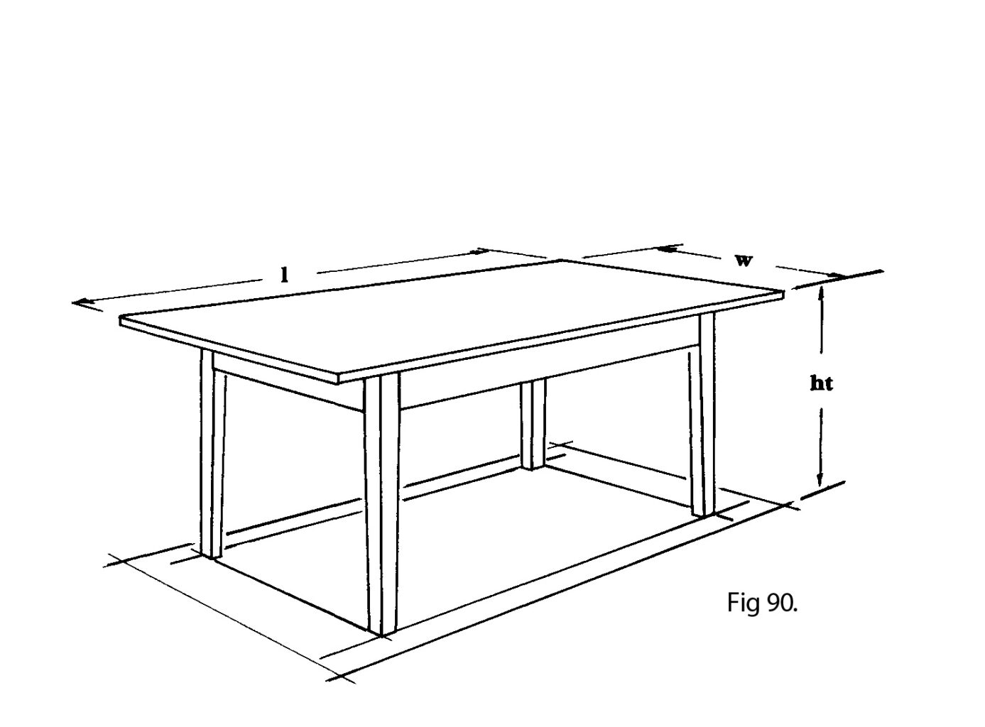
The answers to these practical questions will give the worker the length, the width and the height required. From these three figures a number of design sketches may be produced and the best one selected (Fig 90, for example).
Working drawing
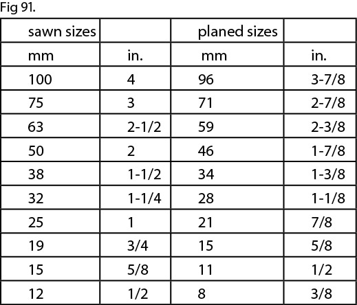
From the design sketch it will now be possible to build up a working drawing. For items of coffee-table size a full-sized drawing is an advantage; larger items must of course be drawn to scale. These full-sized drawings can be drawn on decorator’s ‘lining’ (ceiling) paper. Before making a start the following table of ‘finished sizes’ should be consulted (Fig 91).
The sawn sizes are those used by the timber yards when sawing logs into boards. The finished sizes are those to which the sawn boards can be planed, either by hand or by machine. This figure is both the maximum which can be obtained from the sawn board and also the size marketed as a planed board. In planning component sizes these sizes should be kept in mind in order to use wood with the greatest economy. A reduction of thickness of 1mm (1/16in.) may afford a considerable cost saving.
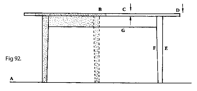
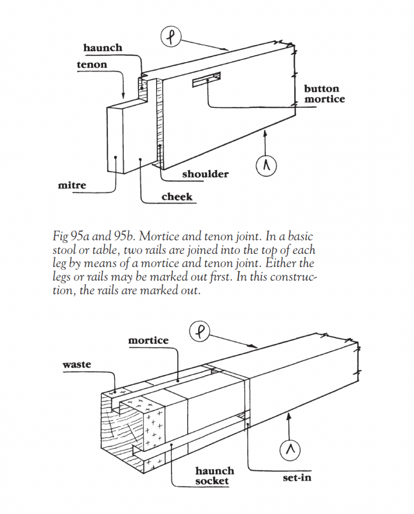
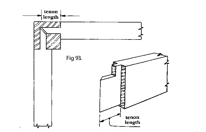
The working drawing (side view) (Fig 92) is built up as follows. Draw the ground line (A) then draw the top of the table (B). Consult the finished sizes and draw in the top thickness (C). Mark this off to length (D). Consider the overhang and draw in the outside edge of the legs (E). Consult the finished sizes again and draw in the leg thickness (F). The top rail (G) is drawn in next, wide enough to give a good joint but not wastefully wide. This can be made narrower if the extra support of a stretcher rail is given. The end (width) view can be similarly drawn. To save space this can be superimposed on the front view (shaded area). When a proper mortice and tenon construction is to be used (as in this example) the length of the tenon must now be ascertained. This is easily done (Fig 93) by making a full-sized drawing on graph paper. Finally the inside edges of the legs can be tapered below the joint. This design retains the simplicity of an all-right-angle construction.
To obviate frequent reference to a drawing in the early stages it is convenient to produce a cutting list (Fig 94) and to work solely from this in the early stages.
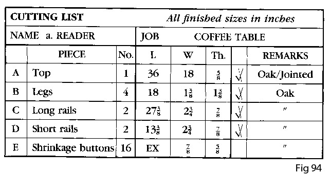
Finished (i.e. final) sizes are used in the list, which avoids allowances being added at several stages in the work. Unfortunately, although there are only three dimensions there are many more names for them, e.g. length, height, width, depth, broad, thick, and so on. The three to be used are length (the distance along the grain), thickness (the smallest dimension) and width (the intermediate size). Width and thickness are often the same size.
To avoid confusion components are often lettered, as in the first column. The remaining columns are self-explanatory except for the blank one. A tick here signifies that the component has been sawn out. A cross tells that the piece has been produced to size and is ready for marking out.