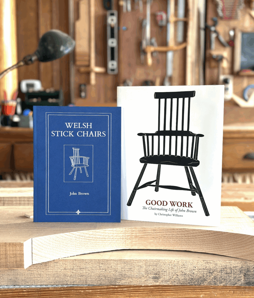
At least once a month someone asks about lid stays for the Anarchist’s tool chest; now I’ll be able to refer them to this post.
Both Christopher Schwarz and I (now) use chains to hold out chests open, but they attach differently. Both methods work. As will multiple other methods, but these are ours.
But let’s back up two ticks. In “The Anarchist’s Tool Chest,” Chris directs readers to leave the back corners of the dust seal a little overlong and cut an angle on them. That will work if you’re gentle with your chest, and don’t use it all the time. If you are not gentle, and do use it all the time, that corner will start to break off – then you’ll need to come up with another method of holding your chest open.
The back corner of the original lid stay (after years of use), as shown in the book.
After the back corner of his dust seal started to show its years, Chris added a rigid aluminum lid stay, held in place by knurled knobs. The problem – if you can call it a problem – is that to use it, you had to unscrew the knob, put the stay in place, then screw the knob back in. And reverse that to close the lid at the end of the day.
Chris’ aluminum lid stay.
When I built the ATC I use at the Lost Art Press shop, I decided to add a nickel-plated chain to the outside, because I like shiny silvery things. So I bought a length of chain from McMaster-Carr along with some 3/8″ threaded rod, and found female-threaded finials on a lamp-repair-supply website. I cut two pieces of threaded rod to length, then epoxied them in place in the side of the dust seal and upper skirt. The chain fits over the rod; the finials screw onto the rod. (I’ve used this same approach on a couple of chests built on commission…but I added a threaded insert into the side of the lid and top skirt for extra insurance. Overkill, but I’d rather err on the side of solid when I’m sending out my work.)
It doesn’t look pretty when the finial is off – but it works.
That’s better!
Chris used a different approach, in part, I think, because he already had threaded inserts and knurled knobs from the aluminum lid stay.
A knurled knob and its insert.
He simply screwed both knobs in tight, then bought a dog collar.
The advantage here is that the chain can be removed in a jiffy when Fido needs to go for a walk.
In truth, though, both of us store our chests against a wall – so more often than not, it’s a wall, not a chain, that holds our chests open.
Centre hinges are generally used to hang heavy doors and in positions where ordinary butts would be impracticable. In some cases they have the advantage of being entirely invisible. There are, however, one or two complications in their use with which the inexperienced reader should make himself familiar, otherwise the results may be surprising.
DIFFERING from ordinary butts, these hinges are fixed at top and bottom of the door as in Fig. 1. There are two main kinds, the straight pattern (A), and the cranked type (B). In both the top plate is free to be lifted from the bottom one.
A washer is fitted between them to prevent them from scraping. A third kind (C) is used only rarely for antique work. The two parts are not free to be separated.
Fig. 2. door between ends. Note how end is hollowed out to accommodate door. Fig. 3. method of setting out. Fig. 4. stages in fitting the hinge plate.
It should be realised at the outset that as a general rule centre hinges can be used only when there is a loose cornice, otherwise it would be impossible to fit the door into the carcase.
There are exceptions as will be seen later, but the reader is advised to draw a section of the door in full size, plot out the hinge centre, and try the effect of pivoting by tracing the door, sticking a pin through the centre, and seeing that it works.
Door Between Ends (Fig. 2) shows the best method of hingeing when the door is between the ends. The hinges are invisible and the edge is dust-proof. The cornice (or plinth) must be loose, however. Fig. 3 shows the setting out. Draw in the door and end, and mark a line at 45 degrees from the corner. Put in another line parallel with the door a third of its thickness in from the front. The centre is slightly in from the intersection, this to allow a clearance when the door is opened. Mark the curve by putting the point on the centre and using a radius equal to the distance from the centre to the back of the door. The practical method of fitting is given in Fig. 4. Before the edge of the door is rounded
gauge in the centre (A) and bore a hole the diameter of which equals that of the hinge pin. Drop in the hinge upside down, and mark round. The exact slope of the plate does not matter; it is only the centre which counts. Chop out the recess and screw in the hinge (C). A similar method is followed on the carcase. Another plan is to make a template of the hinge plate in tin plate, making a small hole at the centre of the pin, and using this to mark out. The hollow in the end is partly ploughed out and finished off with the scratch tool.
Fig. 5. Cranked hinge. Fig. 6. Projecting pilaster. Fig. 7. Door in front of end. Fig. 8. Simple way of fitting. Fig. 9. Queen Anne Hinge.
Cranked Hinges. In Fig. 5 the cranked hinge is used. Its advantage is that there is no need to hollow out the ends because the pin is immediately in line with the corner. On the other hand the hinges are partly visible. The application of the same hinge is given in Fig. 6 in which there is a projecting pilaster or moulding. The centre is in line with the front edge of the door and is a trifle farther in than the corner of the pilaster. A loose cornice is needed in both these cases.
The door is in front of the ends in Fig. 7, and as centred no hollowing-out is necessary in the carcase end. It is not essential that cornice is loose. The fittings are cut in and the parts screwed in before the door is in position. The plate at the top of the door is next unscrewed and its pin put in its hole in the plate fixed to the carcase. Then, by dropping the bottom pin into its hole, it is possible to slide in the top of the door so that the hinge plate goes into its slot. The screw holes are naturally revealed when the door is open, enabling the screws to be put in.
Simple Method. Fig. 8 shows how the hinges can be invisible when the carcase end is not hollowed out (the door is between the ends). It means that the door must be slightly rounded, and the appearance is naturally not so good as that in Fig. 2. It is, however, simple. If the cornice and plinth are fixed the recess for the plate at the top must be continued through to the end as shown by the dotted lines. This enables the door to be passed into position in the way described for Fig. 7.
The special hinge in which the parts cannot be separated (C, Fig. 1) is shown in Fig. 9. Queen Anne furniture usually had centre hinges of this kind. The centre stands clear of the door. A loose cornice is not necessary because the hinge can be slid in afterwards. It is always as well to obtain the hinges before setting out the opening of the door. It saves mistakes.
Fig. 1. Simplest form of square shooting board. Fig. 2. Alternative pattern with detachable mitre stop. Fig. 3. Mitre shooting board. Fig. 4. Square board with one end raised. Fig. 5. Donkey’s ear mitre shooting board. Fig. 6. Board for wide internal mitres. Fig. 7. Waste piece to prevent edge from splitting. Fig. 8. Wood planed at angle in its width. Fig. 9. Wood planed at angle in thickness. Fig. 10. Angle in both width and thickness.
Although the shooting board is a well-known appliance in the workshop, we are frequently asked by readers for more information about it, and we therefore give here the chief types and their use.
The purpose of a shooting board is that of planing the edges of thin wood, either to form butt joints, to make the edge straight, to trim an end square, or to form a mitre. Normally the edge is made square, though in special cases it can be at an odd angle, as we shall see. If you tried to plane the edge of a piece of thin wood in the vice it would be difficult to hold the plane square and it would be liable to wobble. When the shooting board is used, the wood is held flat on the upper step, and the plane is worked on its side on the lower step, all wobbling being thus eliminated.
Types of Shooting Boards. The simplest form of shooting board for square trimming is given in Fig. 1. It can be of any length from about 18 ins. upwards in accordance with the size of the work to be trimmed. The upper step might be from 4 ins. up to about 6 ins. wide, and the lower one should project far enough to take the largest plane in use—say, 4 ins. At the far end a stop is fixed, this fitting in a groove. The near end is at right angles with the working edge, but it is tapered in width, partly to simplify fitting, and partly to enable it to be driven in with a dead tight fit. After being knocked in, screws are driven in and any projection is trimmed off flush.
There are one or two points to note. Firstly the heart sides of the two pieces face each other, so that in the event of shrinkage the twisting tendencies are opposed. Then again, ledges or battens are screwed to the underside, also to help in keeping the parts flat. Along the under-corner of the top platform a chamfer is worked so that any dust which may accumulate will not interfere with the true running of the plane. So far as thickness is concerned, the upper step should bring the work to about the middle of the plane—7/8 in. wood is about right.
A rather more elaborate type of square board is given in Fig. 2. The two parts are fixed to two or more notched cross-battens, a slight gap, say, 1/8 in., being allowed between them to allow dust to escape. Such a board is more likely to keep flat but will not produce better work. If desired, a detachable mitre stop can be fitted with dowels, though generally it is more satisfactory to have a separate mitre shooting board, as in Fig. 3. The construction of this is similar to that of Fig. 1, except that the stop recess is cut in at 45 deg.
Yet a third kind of square board favoured by some workers is that in Fig. 4. In this one end is raised so that as the plane passes forward a different part of the cutter comes into operation, thus spreading the wear over a wider length of edge. It is satisfactory providing the cutter of the plane is sharpened with its edge perfectly straight. Otherwise the shaving will be thicker in one part of the cut than in another.
Mitre Shooting Boards. The board normally used for small mouldings and for wood mitred in its width has already been dealt with in Fig. 3. When wood is mitred in its thickness, however (as in the case of, say, a plinth) the donkey’s ear board in Fig. 5 is used. The construction is obvious from the illustration. The piece beneath, running along the length, is to enable the board to be held in the bench vice. External mitres are trimmed in this way, the wood being held so that the plane always cuts into the moulding, so avoiding splitting out. Internal mitres need the board in Fig. 6. The stop of this could with advantage be fixed in the middle instead of at the end so that the moulding could be placed at either side of the stop, enabling the plane to work into it. Note the dust groove.
Use of the Shooting Board. When the end of a piece of wood has to be trimmed square it is held against the stop, and the plane worked so that its sole bears against the edge of the upper, step. As the plane is worked, the wood is pressed steadily against the plane. To prevent the far corner from splitting, the corner can be chiselled off. Should, however, the wood not be wide enough to permit this, a waste piece with its corner chiselled can be held against the stop as in Fig. 7. Thus the far corner of the wood is supported and is so prevented from splitting. Note that the waste piece should be somewhat thicker than the wood being planed. In the case of a joint being planed the method is somewhat different. The wood should overhang the edge of the upper step by about 1/4 in. or so. The joint is planed true by virtue of the trueness of the plane itself. The latter does not touch the upper step. Remove shavings from the centre of the wood until the plane ceases to cut, and then take a couple of shavings right through. If the plane is accurate (and is long enough) the joint will be straight. It may be necessary to take an extra shaving where needed, but it will not be much out. It is better to rely on the truth of the plane rather than to keep it running along the step—unless the wood is quite short.
Incidentally, always have one board face side uppermost and the other face side downwards. In this way the two will go together in alignment, because if the edge is not dead square (possibly owing to the plane side not being square with the sole) the two angles will cancel out, so to speak.
Odd Angles. Sometimes several ends have to be trimmed at an odd angle, and, when the angle runs across the width, a piece of wood planed to the required angle can be placed against the stop as in Fig. 8. Thus any number of pieces can be planed to the same angle.
When the angle is across the thickness, an angle piece can be used as in Fig. 9, the wood being placed above it. Fig. 10 shows how compound angles which occur in both width and thickness can be dealt with. The two angle pieces are prepared to the required angles first, and the wood placed as shown.
The straight cupboard lock is screwed directly onto the inside of the door with no preparation, hence no description of the method is required. For quality work something better is required. This is the brass cut lock (Fig 447): ‘cut’ meaning cut into the door. The cut drawer lock is similar except that the keyhole is at right angles to that of the cupboard lock. In buying a cupboard lock specify whether it is to go into the right- or left-hand stile.
Prepare for marking by setting a marking gauge to the distance of the key pin (Fig 448). Mark the chosen position for the keyhole with a square on the face of the door then carry it round onto the edge. The gauge marks the distance from the edge (Fig 449). At this stage drill a very small pilot hole for the pin. Offer up the lock to the centre line and mark the length of the box on the door edge (Fig 450).
This is an essential method because on some locks the pin is by no means in the middle of the lock. Mark out this primary cavity with a square and gauge. Weaken the wood with a number of diagonal sawcuts. Waste can then be removed by chisel. Use the simple hand router to complete the process to depth (Fig 451).
Hold the lock in place and scribe round it. Remove the waste to produce the second cavity (Fig 452). The keyhole can now be shaped using a larger drill and a coping saw. It may be finished with a round and a thin warding file. The keyhold is often left like this, but to prevent wear as the key is inserted an escutcheon may be fitted. The brass insert (Fig 453) requires the opening to be carefully filed out until the escutcheon can be pressed in with a G-cramp. Alternatively an escutcheon plate can be made from ebony, rosewood, bone, ivory, etc, and let into the door, either flush or slightly proud. A great variety of shapes is possible (e.g. Fig 454).
For fitting a drawer or till lock the routine is virtually the same. The socket for the bolt must be cut into the carcase. The door is closed with the bolt out, from which the length marking can be taken. Width markings can be made with a marking gauge (generally the points of a mortice gauge will not close sufficiently). Make due allowance for an inset or outset door. An alternative method favoured by some workers now is to ink the bolt end thoroughly with a thick felt marker and to quickly make a print with this before the ink dries, either onto the wood or onto a piece of masking tape. A brass plate can be recessed into the carcase to take the bolt. Unfortunately these are not usually for sale with the lock and must be individually hand made (Fig 455). (Making one by hand is an easy job – saw a piece of thin brass, file it to shape and drill holes in it for the screws.)
These are thicker than the glued-up panels one could use for a tool chest , but you get the idea.
Q: Rather than glue up a bunch of my reclaimed pallet wood, I’m thinking about using some pre-formed “project boards” from the big box store to build a Dutch tool chest (further glue-ups in the house have been outlawed, so it’s either that or wait until it’s warm enough for Titebond in my unheated shop). I’m not too worried about the source material looking like a bowling alley for Smurfs, but I question whether milk paint will stick to something that appears to be 30 percent glue.
And because they also sell a 16″ project board, I thought I’d ask if either of you have seen a DTC that deep. Seems like I’d have to make it 36″ wide so it wouldn’t tumble over, and at that point, I might be better off with an English chest. What are your thoughts?
A: You can certainly use “project boards,” but there are a couple of cons: they cost about twice as much as gluing up your own panels from 1x, and they are often moisture-laden. They might look flat and inviting while sitting there all shiny in their plastic wrap, but remove the plastic and they might cup like a Pringle. But they might not. It’s a crap shoot.
For a Dutch tool chest, however, a 1×12 is wide enough for all but the lid. In fact, that’s the recommended material for those who don’t have access to a jointer and planer (and who don’t want to process material by hand). So were it me, I’d look for the flattest, straightest 1×12 you can find, then go to town. And for the lid, when I’m gluing up panels for a class with our limited number of clamps, I use Titebond and leave the clamps on for only an hour. Now I’m not saying you should…but surely there’s an hour in the day when you could get away with it? (Then hide the panel behind the garbage can overnight while the glue fully cures.)
But yes, milk paint will stick to the project boards – but if you’re at all concerned about it, you can apply a barrier coat of dewaxed shellac between the raw wood and the paint.
And sure – you can make a Dutch tool chest 16″ deep (which will end up at 17-1/2″ after you attach the front and back). In fact, it’ll be more stable than the usual 12-3/4″ deep DTC). I’ve seen them in all sizes. The only drawback with making it deeper (or larger in any dimension) is that it’s no longer as portable.