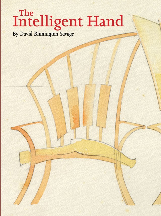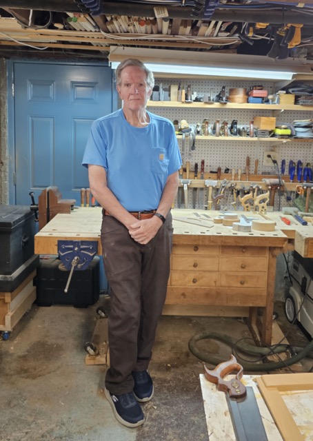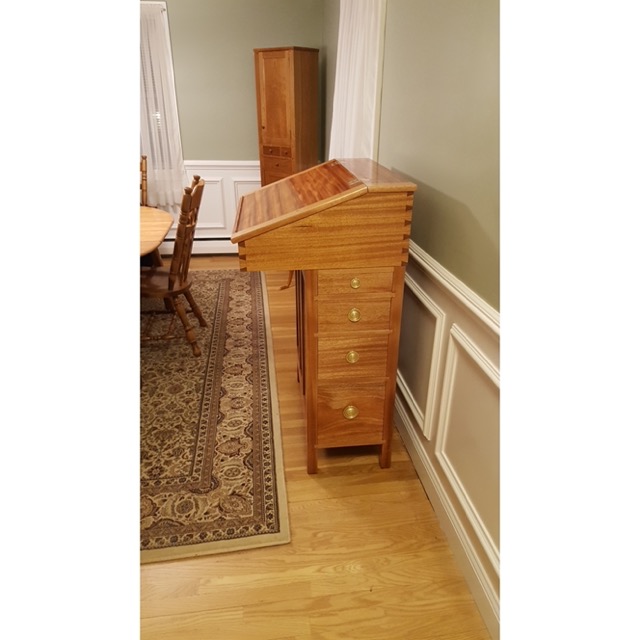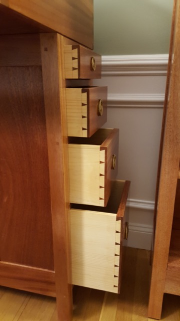
The following is excerpted from “The Intelligent Hand,” by David Binnington Savage. It’s a peek into a woodworking life that’s at a level that most of us can barely imagine. The customers are wealthy and eccentric. The designs have to leap off the page. And the craftsmanship has to be utterly, utterly flawless.
I am jumping now to what a student experiences during the first week at Rowden. I am doing this because it all fits together. Without the doing, the making, the faffing about in the workshop, all the drawing and waking up, there is no context for when you become a designer and a maker.
It’s not good enough to sit in a nice clean design office and get your sweaty minions to make for you. Making is what you do. Remember William Morris, and how he was always fiddling with making something or other. Fail to grasp this, and the maker will always be in charge of the dialogue.
“No boss, that won’t work – you need three fixings there.”
You need sufficient understanding and knowledge to argue. You need to know enough to suggest a different fixing, and to maintain the smooth identity of your design.
So pick up that plane. It’s on its side on the benchtop. Wait – maybe first let’s have a look at what we have here. There is a proper full-sized cabinetmaker’s workbench, about 7′ long. It has a newly planed, flat top. The top is beech or maple, and about 3″ thick; the undercarriage is similarly heavy. A good bench should be solid, and not gallop about the workshop the moment you put the pedal to the metal.
Look at that benchtop. Many makers may have worked there before you, but it should be in pretty good condition – if not unmarked by their work, it should be at least a respectable surface. There have been accidents, yes, that caused the odd bit of damage – but it’s a dead-flat surface. We need flat, especially around the end vice, because that is where we work. The flatness of the bench transfers to the job; a hollow near the vice would show up in thin components planed on that bench. The bench has a front vice and an end vice. Working with these vices will be dogs. Whuff, whuff. No – these are pegs that fit in holes in the bench; they are used to secure your work.

The bench is probably the most important tool you will ever encounter as a maker. Later, you will make your bench; it will become the foundation upon which other work will be made. Right now, you’ll use one of the Rowden benches. Bench height is important. Stand alongside the bench; let your arm hang and bend your elbow just above the bench surface. Now spread the thumb and index finger of your opposite hand. Add that distance to your elbow. This is your bench height.
It’s good to work with a high bench because it protects your back. Much of your work will be done not with your arms and shoulders, but with your trunk – the core muscles – and thighs. This again will protect you from injury. There will be times when you need to get up higher and get on top of a job. Then, use a small “hop-up” – a 3″-high box that you stand upon. This lives under the bench’s bottom rail.
Then there is a bench light. It should be a decent, bright source of light that you can direct into the dark corners of your work. Without a good light you will not be at all times able to see where you are going. A quick maker will be pulling that light around as they move about the job. You need to see the line as you cut.
Then there is a box of hand tools – yours until you can sensibly choose your own. These are prepared tools; all edges have been sharpened by Jon Greenwood to a keen edge. They should all work straight out of the box. All the boxes are different; they hold the same tools but from different suppliers. Spend time trying out different chisels and gauges to help you make informed buying choices. Hand tools have to fit your hands comfortably; different brands offer different solutions at different prices.

With these three – a bench, a light and a box of basic hand tools – you can make a lot of things and need nothing more. Machine work can be done by a local shop; pay them by the hour. You might want some power tools to help out later on, but they are not for now. Most machines are about saving you effort and energy; you want to engage them for those reasons – not because a table saw is more accurate than you are at sawing a straight line.
On the bench, there is a piece of walnut, about 18″ by 2″ or 3″. This is to teach you about wood and tools at the same time. Look at the wood. It has been selected because it is mild and well-mannered. It will have a sawn surface, but you will be able to see the grain of the timber. Think of it as the fur of a cat – which way would rough it up, and which way would lay smooth, if you stroked it? That’s the way you plane it, smooth. Place it the right way around between the dogs and tighten the end vice to just nicely hold the job.
This is the bench doing its job in superb fashion. Now you are free to dance about the workshop, waving a No. 6 to your heart’s content. You don’t have to hold the job – it’s fixed in solid position on the benchtop. All actions now are down to you – how you hold and present that edge to the job. This is you, a sharp edge and a piece of timber. Listen. Attend to what that sharp, well-adjusted tool tells you about the surface in front of you.
Is the note the plane makes a nice, high WHUZZ, or is it getting lower, telling you the edge is getting dull? Watch the shaving as it emerges over the frog – is it a clean, full-length shaving or is there a slight hollow just over there? You want information about that surface; the plane is your primary tool of inquisition.

Consider your arms and shoulders during this process. The work should be coming from your trunk and thighs, not your arms. Imagine a piece of string tied around your plane handle and attached to your right nipple. If you push with your arms, it will pull on the string and hurt. Instead, use your core and legs. A long shaving then becomes like a dance step: forward step, forward step, forward step.
Plane a dead-flat surface on one of the 3″-wide faces. This is your “face side.” It is important, as this is the side from which all other faces are measured; get this wrong and you are in the poo. From day one, hour one, you are faced with quality. Screw this up, go too fast and slip it in under the bar, and it will come back later to bite you in the bum.
Flat is a terrible monster and can drive a newbie bonkers. But don’t let it get you. The sole of your plane is flat – I promise you – so use it. First, let’s look at the side-to-side movement of the plane. As you take a shaving, you can get it only about 1″ wide from the middle of the mouth of the plane – maybe less. If you are observant, you will see that the shaving is slightly thicker in its centre, thinning to nothing at the edge. This is deliberate; you want this.
Run the plane down the job, aiming to get a complete shaving for the whole length – then run another alongside it with a little overlap. If necessary to help you visualise, put a pencil mark across the job and plane it off. Suddenly, this is fun! The plane is working and you are doing the job – you are almost up to your knees in shavings. But the joy of taking long, ribbony strips of fragrant walnut is suddenly ruined by Jon Greenwood coming to your bench with a straightedge.
“Let’s see how flat it is.” What is usually the case is that you’ve been planing up onto the job and down off it, creating a crest in the middle. So, you learn to overcome this by applying more pressure to the plane’s toe as you come on to the work, and to the heel as you come off it.

Now check the surface with a straightedge, and hold the job up to the light and see what is going on. (You have a straightedge on the side of your plane; many skilled makers use that, as well as a purpose-made straightedge, for this and other jobs.)
High points can be removed with stopped shavings that address that area. As you approach flat, back the iron off to produce the finest shaving; this will allow the sole of the plane to have more effect. You might find yourself chasing a minor bump. Don’t do this; try taking a series of fine stopped shavings to the centre of the job, leaving pencil marks on at either end. Then, with three full-length passes, go right through, clearing off the pencil marks at both ends. There you are, nearly there.

Now check it for wind (that’s pronounced “whined”) by using winding sticks – one at each end, and peer across them from one end. Wind is twist. You can have a seemingly flat surface that is actually the shape of a propeller. If the winding sticks are out of parallel, they will visually tell you. This is the last check. You now have a face side to be proud of.
Mark it with a Face Mark, cannily pointing in the direction of grain – the direction the plane or machine must follow. It also points to the Face Edge which is the second surface. This is also a primary surface from which others are measured, so “heads up.”
Remember these steps. You may never do them again with a handplane but you will certainly do them with a pile of timber and a machine shop. The steps are identical: Face. Edge. Width. Thickness. End. Length. We use “FEWTEL” as a way to remember the order. You’ve just finished the first one. Now it’s on to the edge.
The objective is straight and flat on the narrower surface of the edge and, this is crucial, square to the face. Use a square to check this. (A good square can keep you safe; a rotten one, one that has been dropped, is a traitor in the camp that will undermine all your work.) Start off by sliding the stock of the square down the face side, and watch how the blade travels down the edge, looking for gaps between the wood and the blade. Use a bright light behind you to really see what’s going on. A square can easily be banged onto the job and tell you lies. Don’t let it.

Adjusting an out-of-square edge requires a well-set-up plane and some knowledge.
First, look at the plane. The blade, as you noticed earlier, is just a little curved – not straight across. This is important. This gives you the shavings you have previously enjoyed, with thickness in the centre tapering to nothing on the edges. Now look how that blade is set up in the plane body. Look down the sole from the toe, and you will see the thicker, dark shape of the blade in the centre fading out on either side.

This curve gives you the opportunity to adjust an out-of-square edge. Check which way the edge is out of square, then move the plane to the left or the right. What? Yes – look at the way the edge is out of square – it’s higher on either the right or the left. The centre of the plane blade takes a thicker shaving than the edge. So, shift the plane body to the left (or right). Run it down the edge and see a thicker shaving come off that side and nothing come off the other. Without that curved blade, you would not be able to adjust the edge in so accurate a way.
So, engage your brain and eyeballs before engaging the plane. Analyse the situation. Do you need more off here or over there? The square will help – again, register the stock on the finished face and slide the blade down the edge. Use your damn eyes. Hold the job and the square up to the light – don’t be lazy.
Once it’s square and straight, you have a Face Edge (the second letter of FEWTEL). Put a small “f” on the edge, adjacent to the face mark. You can, if you want, lean it in the direction you want the edge to be worked. Good job. Move on to “W” – width.

This is a surface parallel to your Face Edge, and also must be square and straight. Now you need another tool – a marking gauge. Popular at Rowden are simple wooden gauges that (with a little work) scribe a clean line. However, there is another type, a cutting gauge with a small wheel on the end that I find is simpler for the beginner to use. Both are fine. Toolmakers want us to have both marking gauges and cutting gauges, so that they can sell us more tools. I believe in fewer tools that work better. A single sharp gauge should be able to scribe a sharp line both with and across the grain – but you will need a few gauges because they are often left set up for stages of a job.

Take the job, register the gauge off the Face Edge, and scribe a line as close to the sawn width as you can. Make sure it goes all the way around the job. Keeping its stock against the Face Edge will be tricky at first; take gentle stokes to avoid digging into the job.
Now, before we go any further, let’s have look at that little wheel that made that scribe line (if you’re using that type of gauge). Note that it is beveled on one side and flat on the other, and in this case the flat side is facing the stock of the gauge and the bevel facing the outside.
Plane or pare the edge to approach the gauge line. Try to do this evenly all round so there is a little bit of gauge line flapping all around the surface. Then take one plane pass down to the actual line. Smack on.
Now use your gauge, registered off the flat Face, to mark the thickness all the way around the job. Plane to the line, using the same process as in Step 1. Now you have the T in FEWTEL. Jon will come around with a caliper to check the thickness, to within 0.2 of a millimetre. (It should be 0.1, but we are cutting you bit of slack here.)

I had a great student named Martin Dransfield, a former Yorkshire miner, who stayed on and worked for me for a while. A student asked Martin, “How do your joints come up so tight and clean?” Martin, being a Yorkshireman, is a man of few words. He paused, rubbed his chin, then said, “Well tha’ just cuts to the f-ing line.” Which is true. Leave it on and you are effed. Go past it and you are equally effed, but in the other direction.
Thank you, Martin. You are well remembered for your accuracy and your economy of language.

A word on marking-out tools. A cutting gauge, with its bevel on one side of the wheel, is one of a family of marking-out tools that give you a perfect dimension, not an approximate dimension. Mark with pencil and you get approximate. A pencil line has thickness. The marking knife is another tool in that precision family. My personal favourites, made by Blue Spruce Toolworks, are expensive, but you get what you pay for. The blade is long, thin and sensitive. What do I mean by sensitive? Will it take offence if I shout at it, go off in a huff and roll off the bench? No, I mean it will enable me to click that blade into an existing scribe line and I will feel that click in my fingers. That’s what you need from a good marking knife.

Marking with a pencil is fine for some jobs – but not the next one. You’re now at the “E” and “L,” the End Length, in FEWTEL. Place your square across the Face Side, with the stock on the Face Edge. Hold it firmly between the finger and thumb of your off hand. Pick up your marking knife with the bevel facing the waste and strike a nice firm line against the blade of the square. The line should be clear and clean from corner to corner.
Now you need to transfer that line to the face edge. Secure the job in your vice and put the knife in the existing line right at the edge of the job. Make sure the end of your knife pokes out a little. Now slide the square right up tight to it. When you are up and snug, remove the knife then use it to strike a line across the Face Edge. If you are spot on, the line will be a perfect continuation of the line on the Face Side, and you can carry it on around the work to meet the Face Side line. If it doesn’t meet up one of two things have gone wrong: you’ve mismarked around a corner or the job is not square.
If the marking out is wrong you have no chance of good work. Step back to find out the problem, and start again – either the planing or the marking out, as needed. Engage brain before plane.
I am making this point: Making is an intellectual and creative challenge. It demands that you engage fully with every atom of your being. Your full concentration. Otherwise, you will mess up.
The essence of this is that there are no shortcuts to quality work. There are lots of easier, quicker, lower-quality ways that suit lots of other situations, but if you want to do it right there is no shortcut. We see this penny drop with people; it may take a few days, or a few months. Tom, a student with us now, sat with me recently on a log of Western red cedar and said, “David, I have had a really, really, great life, and this has been the very best year, so far. However, if I had come for a trial week I would have run a mile. It took me weeks to see that there is no shortcut.” Thank you, Tom.
This “Doing Thing” isn’t easy. You need to listen to the tool in your hand. That blade has an edge engaging with the infinitely variable material before you: timber. That cutting edge in your hands is the closest you will ever get to understanding this material. The distance between you and it is, at this point, the shortest it will ever get. The information is traveling down that blade into your hand. But do you have the wit to receive it? Our bodies are wonderfully receptive information centres. The body feeds us with information. Do we listen well enough to the sound of the blade in the timber? Do we listen to the note the saw is making, to the feel of the chisel in our hands? Do we weigh the push the tool is requiring and look quizzically at the edge of the chisel? I hope so.
This is why sharpness is so important. With sharpness you have less shove and more sensitivity, control and information. Dull tool/dull maker.
We are asking you to use your eyes in a new and more intense way. This opens the door to learn drawing (more on that to come) for each stage of the process. The ability to draw quick bench notes is an essential skill in making things; it enables us to resolve what’s going on inside that joint.
The eight-week hand-tool initiation ritual builds a solid base upon which to learn machines and other processes. This is tiring, ache-inducing, hard-won accuracy. This is accuracy you have never achieved before. That’s control. That’s you in control. I like that.
