FIG. 1. HOW THE APPLIANCE IS USED. The arm A fits over the far edge of the work and is held by the wing nuts Y. Note that the work overhangs at the front edge.
Anyone using the Stanley or Record combination and multiplanes, or indeed any form of rebate or grooving plane, will no doubt have experienced difficulty in holding the work in position when it is too small or too awkward to be held in the vice. Here is a gadget that is extremely useful in overcoming that difficulty.
FIG. 2. PLAN VIEW WITH MAIN SIZES AND DETAILS.
Made of hardwood, it is capable of accommodating material of almost any length, up to 15 ins. in width, and of thicknesses varying by sixteenths of an inch from 1/4 in. to 1-1/16 in. The one side of arm “A” (see Fig. 2) takes pieces 1/4 in., 1/2 in., 3/4 in., 1 in., thick, the other 3/8 in., 5/8 in., 7/8 in. Intermediate measurements from 5/16 in. to 1-1/16 in. can be obtained by inserting a 1/16 in. thick washer under arm A. Other measurements can be arrived at by using thicker washers, though 1 in. is normally ample, anything thicker being suitable for the vice.
The diagrams show the construction of the device and call for little comment. Arm A is attached to slides E by 2-1/2 in. bolts, the heads of which are sunk. Note also that the head of bolt X is sunk below the level of pieces B and D (see Fig. 3).
FIG. 3. HOW BOLT X IS RECESSED.
To attach the device to the bench it is necessary to cut a number of mortises, 1-1/4 in. by 1/2 in., 6 ins. apart along the edge of the bench. Where the vice is flush with the edge of the bench the mortises will have to be cut in the bench top, but where the vice projects any distance an extra fitment can be screwed in position. The mortises in no way interfere with normal work, and once cut require no further attention. Two hardwood stops are then all that are necessary to hold the device rigid on the bench. These should be about 4 ins. long and a tight fit in the mortises.
FIG. 4. METHOD OF HOLDING NARROW WORK.
The method of use is as follows. Attach the device to the bench by means of bolt X passed through one of the mortises. Now drive the stops into the adjacent mortises, allowing the one towards which the planing is to be done to project above pieces B and D. This will act as a planing stop. The rear stop is driven below the level of B and D and serves merely to prevent the device swivelling due to lateral pressure. Here it may be noted that the outer edge of piece B projects a little over the edge of the bench as in some cases it may be required to act as a guide to the plane. Where a long strip is being rebated, for example, the front stop may be driven below the level of B and D and, the device being fixed in the middle of the bench, the bench stop used as the planing stop.
The work is placed on top of the device, its near edge projecting slightly beyond the edge of B and its end against the planing stop or the bench stop. Arm A is slid up to the far edge of the work and bolts Y tightened. Fig. 1 illustrates the method. By this means the work is held rigid.
In some cases, when the work is narrow, the construction of arm A does not permit of the work being clamped down, as the projection of A interferes with the plane. The method then is to reverse arm A, as in Fig. 4 in which case it serves merely as a lateral stop and not as a cramp.
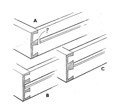
FIG. 1. TYPICAL OPERATIONS SHOWING THE ADVANTAGES OF TAKING THE TOOL RIGHT THROUGH: A. Through groove worked with plough and stopped groove. B. Trenching taken right across and stopped trench. C. Use of plane on straight edge and edge with stops. D. Plain chamfer and one with stops
The practical working of wood is largely based upon an extraordinarily simple fact; a fact which every man who goes in for woodwork, even in an elementary way, soon comes to discover for himself. This is that it is easier to take a tool right through than to stop it short—at any rate so far as hand tools are concerned. Men in the past found this out at a very early period, and traditional methods of construction have been based on and developed around this simple truth, but it is rediscovered daily by every man who picks up saw, plane, file, and so on.
Consider the number of times you experience this; how much easier it is to work a through groove than a stopped one; how simple it is to take a saw right across a piece of wood, but what a different proposition when it has to be stopped short as when sawing the sides of a stopped groove; how straightforward it is to plane an edge straight, yet what a nuisance it becomes when it is stopped at one (or both) ends and you cannot use the plane except at the middle (haven’t you been tempted to plane the edge straight and plant on the stops afterwards!); how a simple chamfer can be formed with the plane in a few seconds, but takes probably ten times as long when it is stopped; and so the list might be continued. These points are brought out in Fig. 1.
Of course, it does not follow from this that grooves are never stopped or that chamfers always go right through. Sometimes you cannot help yourself; possibly the one may be a constructional necessity, or the other so attractive a feature that it is worth the trouble involved. But there is no point in work for its own sake; it is much better to go about things in a simple way, especially when the involved method carries with it no corresponding advantage.
FIG. 2. DRAWER WITH SUSPENSION RUNNERS: Construction at A is faulty for hand work since plough cannot be taken right through. B and C are better
It is because of this that it is generally easy to tell whether a design is the work of a practical man; or, to take another aspect of the same thing, why a design by an artist invariably requires the cooperation of an experienced woodworker to convert it into terms of practical working. A simple example came to our notice recently. The sides of a drawer had to be grooved to fit suspension runners attached to the cabinet sides. They were shown stopped at the front as at A, Fig. 2. Surely no practical man would ever have given such a detail to be worked by hand when it would have been just as easy to arrange things as at C in which the plough could be taken right through before assembling the drawer. In fact the arrangement at B could have been followed, so enabling the runner to afford support almost to the extreme front.
FIG. 3. HOW STONE MASON WORKS HIS MITRE IN A CORNER BLOCK OF STONE
This running-through business is of particular interest because it is largely peculiar to wood, and it is partly due to wood being a natural material which must be used in the form in which it is found (we are ignoring here made-up materials such as laminboard, plywood, etc.). Some materials (metal, plastics, etc.) can be cast or moulded, and projections and stops present no more difficulty than flat surfaces. With timber you fell the tree, convert the log, and then think in terms of so many straight pieces of material. Another point affecting the thing is that wood is comparatively soft so that you can set a metal cutter in a stock (that is, make a plane) and take off shavings, the device having the advantage of helping to make the work straight and true. But of course you have to be able to take the tool through without hindrance.
Perhaps a better appreciation of this point is to compare it with the method used by the stone mason. You cannot use a plane on stone; you have to chip it away with chisel and hammer. There is therefore no point in running through. If a mason has to work a moulding around, say, a window opening, he does not form the joint right at the mitre. Instead he carves a special corner stone as in Fig. 3, this having the two joining mouldings carved in it. Thus we see how a fundamental difference in methods of working has evolved a technique peculiar to the material, this basically affecting the design.
FIG. 4. (left) MASON’S MITRE APPLIED TO WOOD. FIG. 5. (right) NORMAL MITRE USED BY THE JOINER
This brings us to an interesting point. The carver in wood uses tools and methods of working which are similar to those of the sculptor in stone. He uses gouges and chisels as distinct from the planes and ploughs of the joiner or cabinet maker. Consequently the running-through idea does not apply to him. When therefore a wood carver makes a piece of woodwork he often carves it in the solid rather than joins pieces together, and the mitres of his mouldings are like those of the mason. In fact, the same idea is occasionally carried out in joinery in which a timber framing is used. In Fig. 4, for instance, the joint in the moulding is not on the mitre line, but runs straight across in line with the shoulder of the joint. Clearly the moulding plane could not be used on the uprights, and the corner would have to be cut by the carver. This joint is, in fact, known as the mason’s mitre, and the corresponding joiner’s mitre is given in Fig. 5.
It is an interesting thought that if the technique of woodwork had developed through the wood carver rather than the joiner, the mason’s mitre would probably have become the rule rather than the exception.
FIG. 1. EXAMPLES OF EARLY CARVING. (A) Early Gothic, XIV or XV century. (B) Incised Work. (C) Jacobean. (D) A Favourite Tudor Ornament. (E) Simple Tudor Edging. (F) Elizabethan Design in Low Relief.
From the earliest pre-historic ages man has tried to express himself in some form of decoration, first in flint and then in wood. To a large extent he is dated and the degree of his culture determined by what he has left to trace his existence.
Woodcarving has been a feature in every civilisation, and all through the centuries we find that days, weeks and often months might be spent on the knife decoration of some weapon, tool, paddle, or domestic utensil. It is interesting to note, however, that, when carving first became a recognised craft in Europe, it was devoted to church woodwork long before it reached the humble home. In our own country little carved furniture can be traced further back than the sixteenth century although many earlier church coffers, chests, and seats with carved decoration are to be found.
Just, too, as woodwork design was borrowed from models in stone, the carpenter in his carving followed the prevalent Gothic mode. Early Tudor carving is almost exclusively Gothic in character (Fig. 1, A and B). Occasionally we find crude representations of figures, or of horses, deer, or birds, and sometimes a medallion with a bas-relief head; but as a rule the carver, timid of freedom, restricted himself to geometrical patterns (Fig. 1, C, D, E). Of these there is a great variety, many showing marked ingenuity, but it was not till the Elizabethan period that we have something of the freedom indicated in the type of design shown at F. The “linenfold” panel had been common from an earlier period, but in Elizabethan times cupboards, buffets, four-post bedsteads were freely carved, the bulbous form of pillar and leg (Fig. 3, K) being a feature of the period.
Throughout the different periods it is instructive to note how well adapted the decorative carving was to the general design. In early Tudor days the carpenter trusted largely to simple incised work or gouge cuts, and little was attempted in the way of modelling. Even during Queen Elizabeth’s time carving was kept in low relief, and it was not till the somewhat heavier Dutch influence was felt in the Jacobean age that we find bolder scroll and leaf work.
Mouldings were freely carved, their differing contours offering scope for individual enterprise. As the tool kit developed work tended to become more delicate, till in time certain cabinet makers specialised in carving. The amazing work of Grinling Gibbons in the the seventeenth century may be regarded as exceptional. Influenced by Italian and French modes he was, in a sense, before his time, and no other English woodcarver has ever reached his fame. The brothers Adam introduced a new technique towards the end of the eighteenth century, and their delicate husk festoons and pendants in conjunction with graceful vases, paterae and fluting are more typically British than any other form of decoration bequeathed to us (see Fig. 2).
FIG. 2. TYPICAL FRIEZE OF THE ADAM PERIOD (LATE XVIII CENTURY) Note the use of severe fluting in contrast to the free husk ornament. Adam chimney pieces were almost invariably treated in this way.
Has the carver disappeared? Practically so—at least for the moment. During the nineteenth century he had to rely chiefly on the designer who, discarding earlier British motifs, showed a leaning towards the conventional and more elaborate Italian models. The introduction of manufactured pressed carvings shocked the purist; and later, when “strip detail” came to take the place of hand-carved mouldings, the craft became suspect. This, with the high cost of labour after the 1914 war, drove the woodcarver from the field—an irreparable loss till, perchance, the world again becomes rich.
Turning. There can be little doubt that, to the potter’s wheel, we owe the origin of wood turning. The earliest form of pole lathe, too, has lingered to the present day and may still be found in our woodlands. In the development of wood turning one point to observe is that it did not follow architectural features in stone so closely as, say, cornices, pediments, and mouldings. The craftsman soon discovered that, in wood, much more was possible than in stone. Thus, unless the design was definitely based on some architectural model, the woodworker struck out on a line of his own. This became more noticeable when domestic furniture came to be decorated. On ecclesiastical woodwork the line of the architectural column, tapering from plinth to capital, was followed; but, even from early Tudor days, we find that, in the case of turned legs, the taper was inverted. This is seen in examples such as A, B, E, G and H at Fig. 3. When, however, the turning took the form of a baluster (see D) the taper was usually reversed, or (as in K) the columnar part kept throughout at the same diameter. This freedom from the rigidity of classical Greek and Roman models has been a feature in turning down through the centuries.
FIG. 3. TURNED WORK DURING THE VARIOUS PERIODS. (A) Early Tudor. (B) Elizabethan (also Flemish). (C) Jacobean Twist Turning. (D) Jacobean. (E) William and Mary Period. (F) Chippendale Grouped-Pillar Leg. (G) Leg of the Adam Period. (H) Delicate Sheraton Leg. (J) Split Turning (Jacobean). (K) Elizabethan bulbous column.
In an article which is a mere sketch it is impossible to do more than indicate the features of different periods. Examples, however, are well worth close study whenever one has the opportunity. Very few people understand the problem involved in planning a graceful piece of turning. Everything depends of line and proportion. One thing to remember is that the diameter is the same from whatever angle the column is viewed. On paper, in elevation, a 2 in. square leg looks the same as a turned one of 2 in. diameter; but, when seen from an angle in the finished piece, the turned one appears to be only about two-thirds as heavy as the other. This the designer often overlooks, although he is more apt to make the square leg too heavy than the turned one too light.
The early craftsmen played for safety, and thus in Tudor, Elizabethan and early Jacobean days we find turnings of the “bulbous” type which bordered on the heavy side. A change emerged during the reigns of William and Mary and Queen Anne, till, later, Sheraton gave us examples which, in delicacy, have never been surpassed. Early Stuart work came largely under Flemish influence, but the typical Jacobean “twist” turning, continued through Queen Anne’s reign, gave us a form which has ever since been popular. The nineteenth century failed to produce any new pleasing model, the tendency being to accumulate members without any real meaning. Mass production rather cheapened the craft, furniture makers finding it easier to purchase a set of stock legs than to turn new ones from designs of their own. For this reason it is well to keep before us the old models in which every detail was considered in its relation to the whole piece.
CROSS HALVING WITH HOUSED SHOULDERS The cross-halving joint, with notched or housed shoulders (Fig. 1), is only rarely used in actual practice. In ecclesiastical woodwork it is occasionally seen on a cross, and at times (though less frequently) in outdoor woodwork framing when the timbers are fairly stout.
The cutting of the joint is shown at X. The notching (or shoulder) is never more then one-sixth of the width, and is sometimes less. Although the cross piece is slightly weakened by the shouldering, the joint is really a strong one as in gluing there is an extra hold at each side. The joint moreover is a neat one and has been used effectively for high-class joiner-made estate gates.
FIG. 2. SADDLE JOINT FOR UPRIGHTS
SADDLE JOINT For this Joint (Fig. 2). the name “saddle” is distinctly obvious, especially if it is turned the reverse way; the V-shaped aperture in the post fits saddlewise on the triangular projection in the notching. The joint is used to connect upright posts to sills, or to the head horizontals of similar framing.
In everyday outdoor work it may be hardly worth the additional labour, but for indoor joinery it is a good joint. It weakens the framing much less than a mortise and tenon joint, and there is little effect of shrinkage on it. Its great advantage is that the saddle (the V) keeps everything in alignment. Depth of notch in sill should not exceed one third or two-fifths of the thickness of the timber.
FIG 3. HALVED JOINT WITH DOUBLE DOVETAILS.
FIG. 4. PLAN AND EDGE VIEW OF JOINT SHOWN IN FIG. 3.
DOVETAILED SCRIBED OR HALVED JOINT This (Fig. 3) is a joint which, in former days, was used in better class interior woodwork when pieces of timber had to be lengthened.
When accurately marked and cut the double dovetails ensure against any gap showing. In Fig. 4 the separate parts are shown in plan and elevation. Sections at both ends of the joint (A and B) are also indicated. From these diagrams the setting out of the joint can be followed. For general building the double dovetail involves too much work to justify its general use and it is rarely seen. In the Handicraft Centre, however, the joint has often been used as an exercise, and the home worker who has a flair for accuracy in marking and cutting would enjoy a couple of hours on it.
FIG. 7. SPOKES OR ARMS OF BARROW WHEEL THREE-WAY HALVED
THREE-WAY HALF-LAP JOINT
The rather complicated three-way halved joint at Figs. 5-8 is one of the most troublesome to mark out and construct with flawless accuracy. It has always been widely used by pattern makers, chiefly for the lap-jointed arms of pulley patterns.
In former days, however, the village carpenter knew it and used it for barrow wheels. Fig. 5 shows a wheel with built up rim (the joints probably bridled). Fig. 6 shows the three arms, or spokes, lap-dovetailed to the rim and “three-way lapped”, or, as it is sometimes termed, one-third lapped, together. The separate arms cut and ready for assembling are shown at A, B, C, Fig. 7. For clearness piece C is shown reversed—that is, upside down.
If the centre joint part of Fig. 6 is drawn full size it is worth while setting out the parts. Take the width of arm as, say, 2 ins., and the thickness 1-1/2 ins. Two points may be noted as a guide.
On the width face all the lines can be set out with T square and 60 degree set square. The thickness (1-1/2 ins.) is divided into three in order to get the three planes or steps of the joint. Hence the term “one-third” lapped.
Fig. 8, in conjunction with Fig. 7, will show how the parts are assembled. The “step” of piece A is 1/2 in. thick, the edges of the cut part above being 1 in. Over this B lies at an angle. It covers the flat step of A, but leaves two little triangular gaps (x) (Fig. 8) which are later filled by the corresponding triangular steps marked on C, Fig. 8.
FIG. 8. ORDER OF ASSEMBLY OF SPOKES OR ARMS
Piece C (shown reversed) rests at the correct angle on the halved upper face of B, the little mid-step projections fitting into the gaps (x) left on Piece A. The piece C is the same as A except for these extra triangular steps (x).
When the parts are glued it will be seen how firmly they are interlocked. Incidentally, if the reader can lay his hands on a medium-sized turnip, it is an interesting study to make a small experimental model joint with a penknife. The parts need not exceed 1 in. by 3/8 in. It is not the first time that turnips have been used for model joints.
Are we becoming adjusted to speed? I was talking a few days ago to a factory worker who thinks we are and that men are changing and will go on changing under its influence. “Everybody is working,” he said, referring to husbands and their wives, even children in holiday times. “The pressure is terrific.”
Conversely, so are the tensions. Perhaps these are at the root of the restlessness of some men, who seem to be always on the move, and in the growing number of others who, in their leisure, embark on creative, often very exacting work. With outlets like these, tensions tend to diminish, more so than if a man simply relaxes into complete idleness.
The important difference is that we make our own speed and with this comes the feeling of release. When we want to work quickly, there are the small power tools to take the edge off our impatience. When we want to taste to the full the luxury of unhurried, relaxed work, then we can settle down to a job with all the sober pleasure of an oldworld craftsman, finding perhaps some stray particles of wisdom touch us unaware.
But however we work, the thing of prime importance is to live, really live in the job of the moment so long as it lasts. Once we begin to cast our eyes ahead to the next item on the schedule, away goes peace and back come the tensions. When this happens, reasonable speed looks only an irritant, hands fumble through sheer unmitigated impatience. And that kind of impatience is the very devil in creative work. Unless we are careful, it mars the work, it certainly mars our temper and our enjoyment of the job. For the great thing about craft work when we do it on our own terms, is that it can be so thoroughly enjoyable. It has the power to take a man right out of himself, right into the thing he is doing, an excellent therapy against the stringencies of a busy world.
But the mind, being so much quicker than the hand, can easily betray us, so that a great part of the patience of true craftsmanship comes from keeping the mind reined in, never to be tempted to dream about the following job while we are doing this one, so risking making this one look like an interminable nuisance. “Little by little and bit by bit, that’s the way you does it,” as an old gardener once said to me reprovingly, and it is a good, steadying philosophy when we are getting a bit ahead of ourselves.
As a matter of fact, it is quite remarkable how many men today are learning to take the long view. They may have bought a partly derelict property at a bargain price or have determined to modernise their old-fashioned house, but whatever it is that starts them going the project is often one which has to be carried out over a long period of spare-time work. Some men even put themselves to school first for one or other of the essentials, such as bricklaying, engaging this with some other skill they already have. The result is often first-class. When a man puts his whole mind and will to a job, amateur or part amateur though he be, it is remarkable what excellence he can achieve. The trouble with most of us most of the time is that minds and wills are only half engaged. Put the whole of ourselves into a job and the good thing emerges. What is most noticeable is how readily these men shape down to the steady, progressive, long-term view, neither hurrying, nor unduly worrying, but taking each stage as it comes, dealing with it so thoroughly that care goes a long way towards meeting the demand for expertise. Because their number is now increasing all around, there is almost certain to be a friend or neighbour able to help and advise at difficult moments. And it is not at all unknown for a lecturer at a Technical College, becoming interested in the ambitious projects of his pupils, going out to give them a hand over the tricky bits.
It is a new wave of craftsmanship that has come upon us, born of changed social conditions. Before the war no ordinary householder, however skilled, would have dreamed of attempting single-handed the jobs which his modem counterpart undertakes. It is craft work from quite a different direction, bringing with it an ability and sense of independence which are the best kind of answer to the various pressures which make up the modern world.
It is the ordinary man standing squarely on his own feet, learning to “do” for himself once more and finding quite a bit of enjoyment and an amazing potential in the doing. The general collapse and withdrawal of handicrafts from industry is helping to bring about a revival in our very midst. Truly we are adjusting ourselves to changes of all kinds, not only pace. Pace, indeed, can kill. It can also be exhilarating.