This is an excerpt from “The Woodworker: The Charles H. Hayward Years: Volume I” published by Lost Art Press.
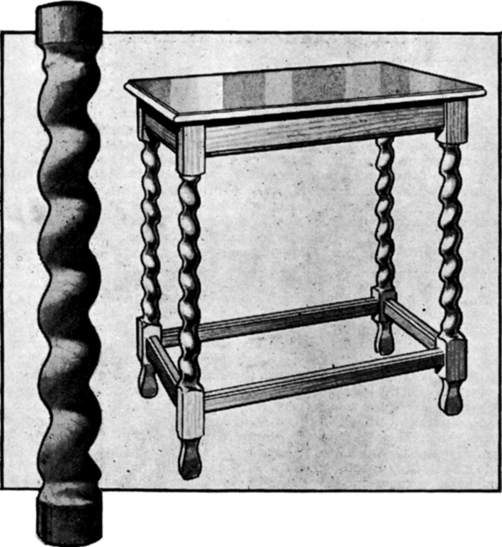
It may interest readers to know that the best twist-turned legs are still a combination of turning and carving, and that when they were first made in the 17th century the lathe played a quite secondary part in the manufacture. In this article we are going to assume that you have no lathe at all and are going to rely upon normal hand woodworking tools plus one or two carver’s gouges. Even the last-named are not essential, but are certainly a great convenience.
Rounding the Wood. Prepare your wood in the form of a square as in Fig. 3, and mark in the centres at both ends with the gauge. Continue the lines along the length of the wood as shown, using a pencil. Mark in circles at the ends, using dividers, and plane off the corners so that the square is reduced to an octagon as in Fig. 4. Finally take off the remaining corners, so rounding it, leaving the pencil lines untouched.
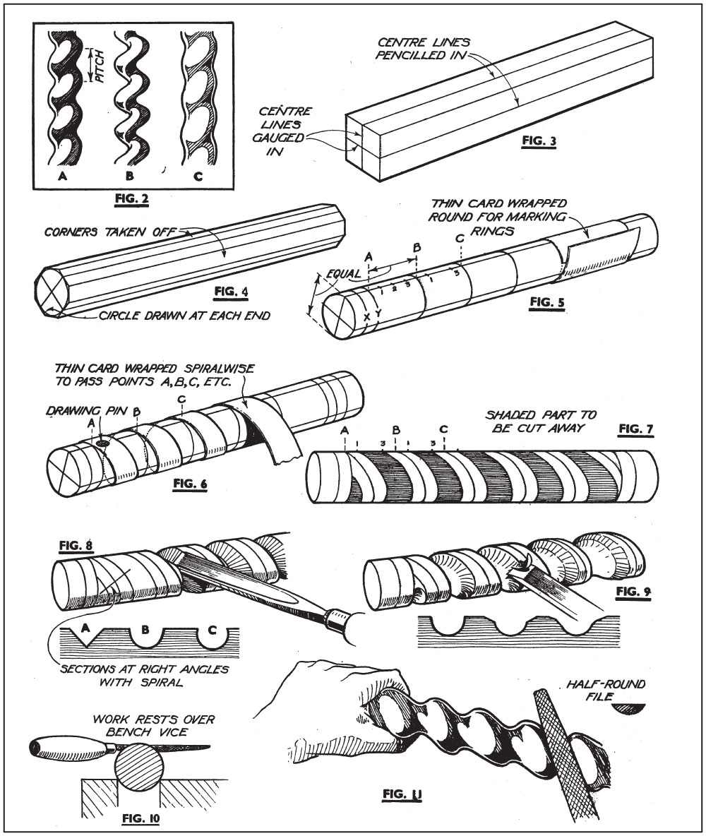
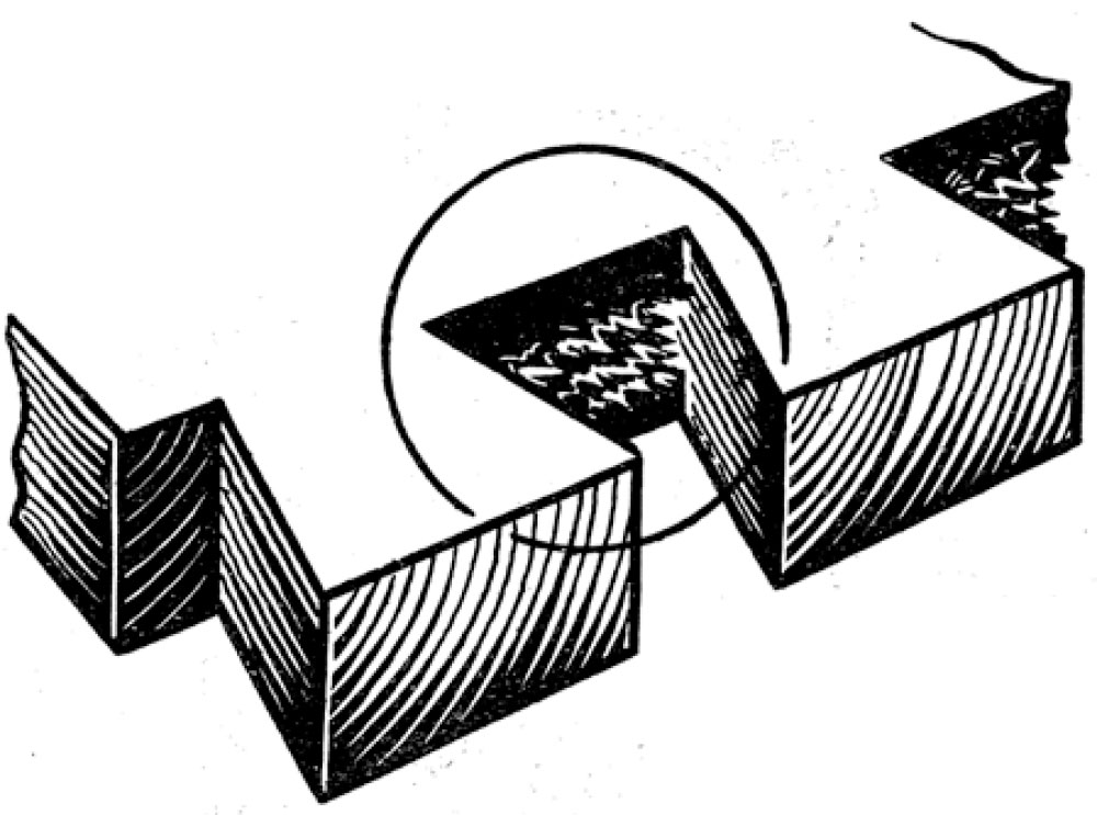
Pitch. We have now the pitch and depth of the twist to consider. When a nut is revolved upon a bolt it rises by a certain amount at each complete revolution. That is its pitch, and a similar idea applies in a twist leg. Glance at A, Fig. 2. The rounded part of the twist at the top of the arrow passes spiralwise round the leg and when it reaches a point vertically beneath it has completed one revolution, and the distance down it has travelled is the pitch. There is no definite ruling about it, but generally the pitch is made to equal the diameter of the wood as in the present example. You can vary it, however, by way of experiment if you prefer.
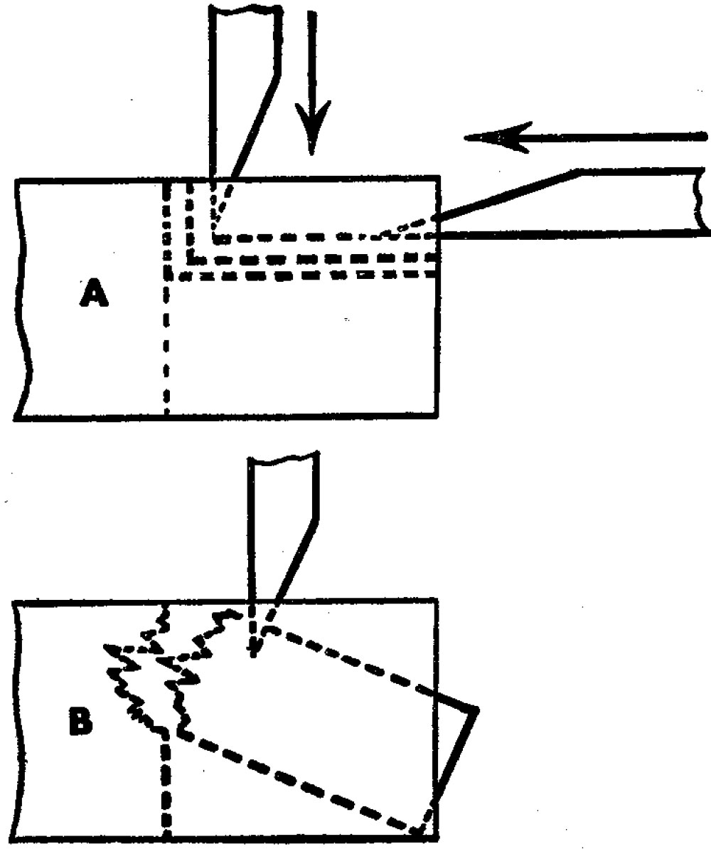
Now for depth. The hollowed-out groove of the spiral can be cut in so deeply that it passes more than halfway through the wood, as at B, Fig. 2. This would be graceful enough, but would have little strength and would so be impracticable for most jobs. On the other hand, it could be shallow as at C, in which case it would appear as little more than an indeterminate ripple along the surface. Obviously something between the two is needed, and you can take into account the work the leg is expected to do. For instance, a heavy chair or table leg would have to be shallower than a spindle which carries no weight. This depth, by the way, does not affect the pitch.
Marking the Spiral. We will assume that the pitch is to equal the diameter, and the next step must be to make a series of rings around the leg, their distance apart equalling the pitch. Thus, assuming the diameter to be 11∕2 ins., the distance between AB, BC, etc., (Fig. 5) will be 11∕2 ins. The rings are easily drawn by wrapping a piece of thin card with a straight edge around the wood as shown.
To mark the spiral, take a length of thin card having one edge perfectly straight and, holding the true edge at the point A, wrap it spiral-wise around the leg, adjusting the position so that it cuts the point B, then C, and so on as in Fig. 6. A drawing-pin can be used to hold the end temporarily. Run a pencil around the straight edge so marking in the centre of the rounded or high part of the twist.
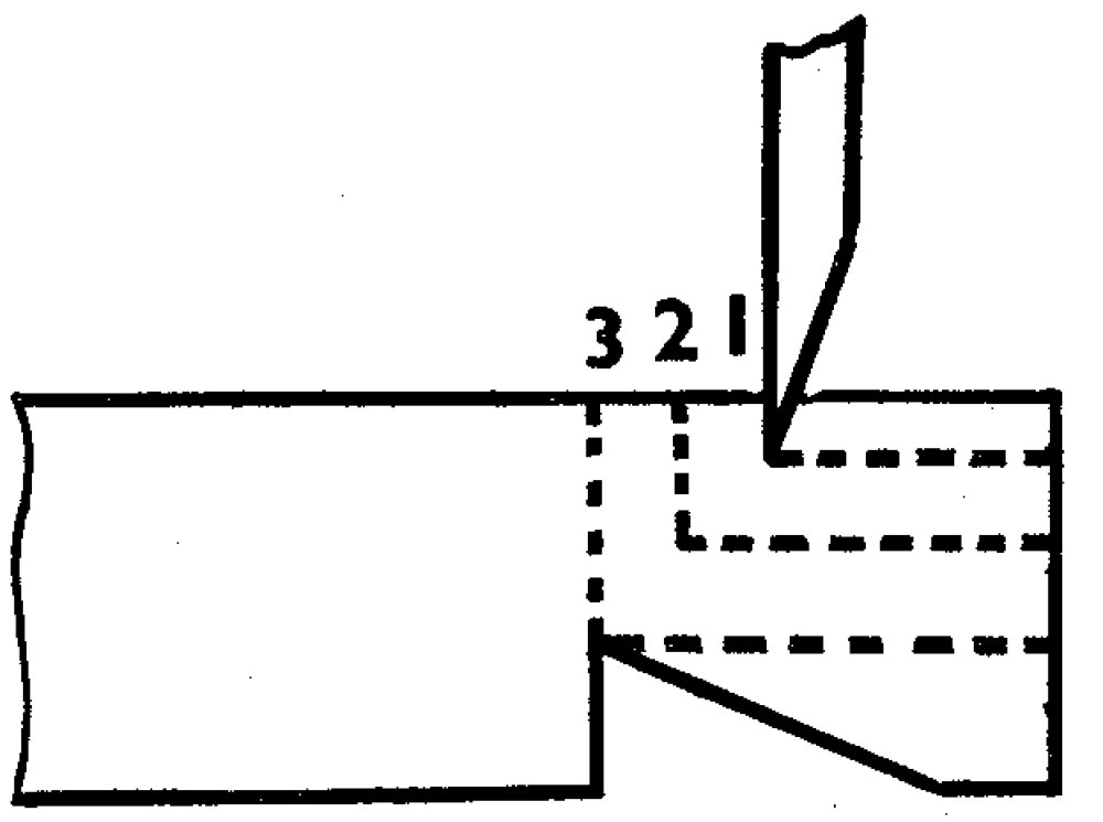
Now turn to Fig. 5. You will see that AB, BC, etc. are divided into quarters, 1, 2, 3. Actually only the points 1, 3 are needed, but 2 is marked in because it is convenient to divide up into halves first. Using the length of thin card again, wrap it again round the leg to pass through the points 1-1, etc., thus being parallel with the first line. Repeat the process, this time making the line cut the points 3-3, etc. You thus have three distinct spirals passing down the leg as in Fig. 7, and it is the wood between 1-3 that is to be hollowed out. It is shown shaded in Fig. 7, and it is in fact a good plan to scribble between these lines on the actual leg so that there is no question as to what is to be cut away.
Incidentally, we may note that it is always as well to have a hollow at both ends of the spiral as the latter can then die out naturally. Hence the rings XY at the ends in Fig. 5.
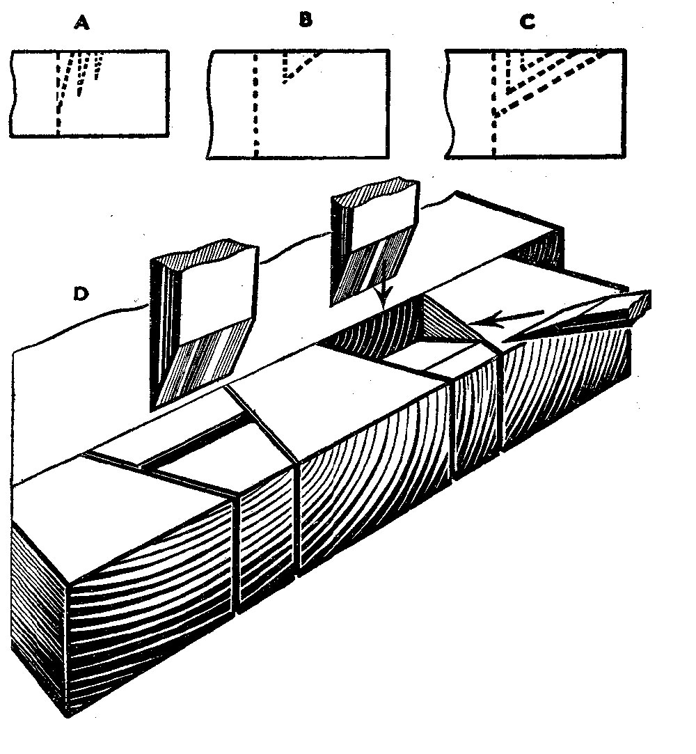
Cutting the Groove. A carver’s V tool is convenient for the preliminary cutting out (see A, Fig. 8), but a carver’s gouge can be used throughout if preferred. Gradually deepen the cut until the sides line up with the pencil lines.
Of course, the direction of the cut will have to change during every stroke and it should be in alignment with the spiral the whole time. The best way of holding the work is in the bench vice, cutting away each exposed part of the groove, giving slight turn, then cutting the newly exposed part, and so on until the whole is completed.
The gouge follows as at B, Fig. 8, care being taken to make the depth as equal as possible throughout. The sides should slope outwards slightly as at B. At all events avoid undercutting as at C. Once again let the gouge follow the line of the spiral.
Finishing the Rounds. Using either chisel or flat gouge, take off the corners now as in Fig. 9. You will find that one side will cut easily; the wood will have to be reversed for the other to be done. Working in this way you will find that the work will aproximate roughly to the finished shape.
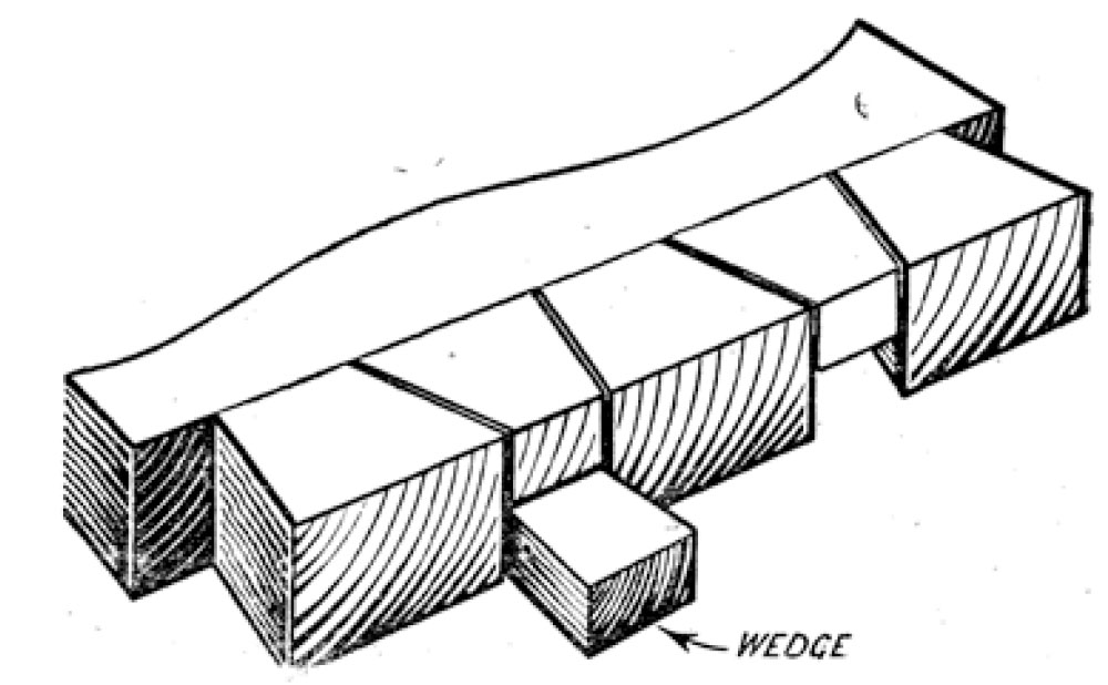
To take out chisel and gouge marks a large round or a half-round file is used.
If a compound movement is adopted the high parts will automatically be taken out. The flat side of the file can be used for the rounded parts. Rest the work just above the vice as in Fig. 10, so that it can be revolved with the left hand whilst the file is used. Note from Fig. 1 how at the ends the round diminishes into the circular hollow.
Glasspaper is used finally, and it is essential that this is thorough. A shaped rubber can be used, but the fingers are also handy. Follow round the course of the spiral using first Middle 2 grade, then finer until you complete with No. 0. In this way you will finish with a beautifully smooth surface.
— MB