Well it took longer than I expected, but we now have all four volumes of “The Woodworker” back in stock and ready to ship. If you order before April 30, you can get all four volumes for $100 with free domestic shipping. That’s $39 off. Plus the free shipping.
Here’s the link to the page. The books are also available for sale individually.
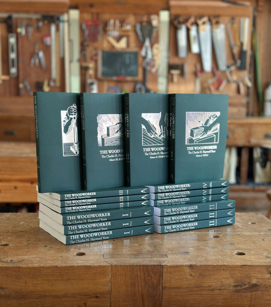
These four books are the backbone of a complete education in handwork. A team of six people (including some extra helpers) worked for eight years to read, organize, scan, design and produce these four books from the articles written and edited by Charles H. Hayward.
As editor of The Woodworker magazine from 1939 to 1967, Hayward oversaw the transformation of the craft from one that was almost entirely hand-tool based to a time where machines were common, inexpensive and had displaced the handplanes, chisels and backsaws of Hayward’s training and youth.
Our massive project distilled the thousands of articles Hayward published in The Woodworker. This is information that hasn’t been seen or read in decades. No matter where you are in the craft, from a complete novice to a professional, you will find information here you cannot get anywhere else.
The books have 1,492 pages total, with thousands of hand drawings and photos. The books are printed in the USA and are designed to last decades. The sewn bindings will lay flat on your bench. The uncoated paper is easy on your eyes.
For more information on the project, including a complete list of all the articles in the books, click here.
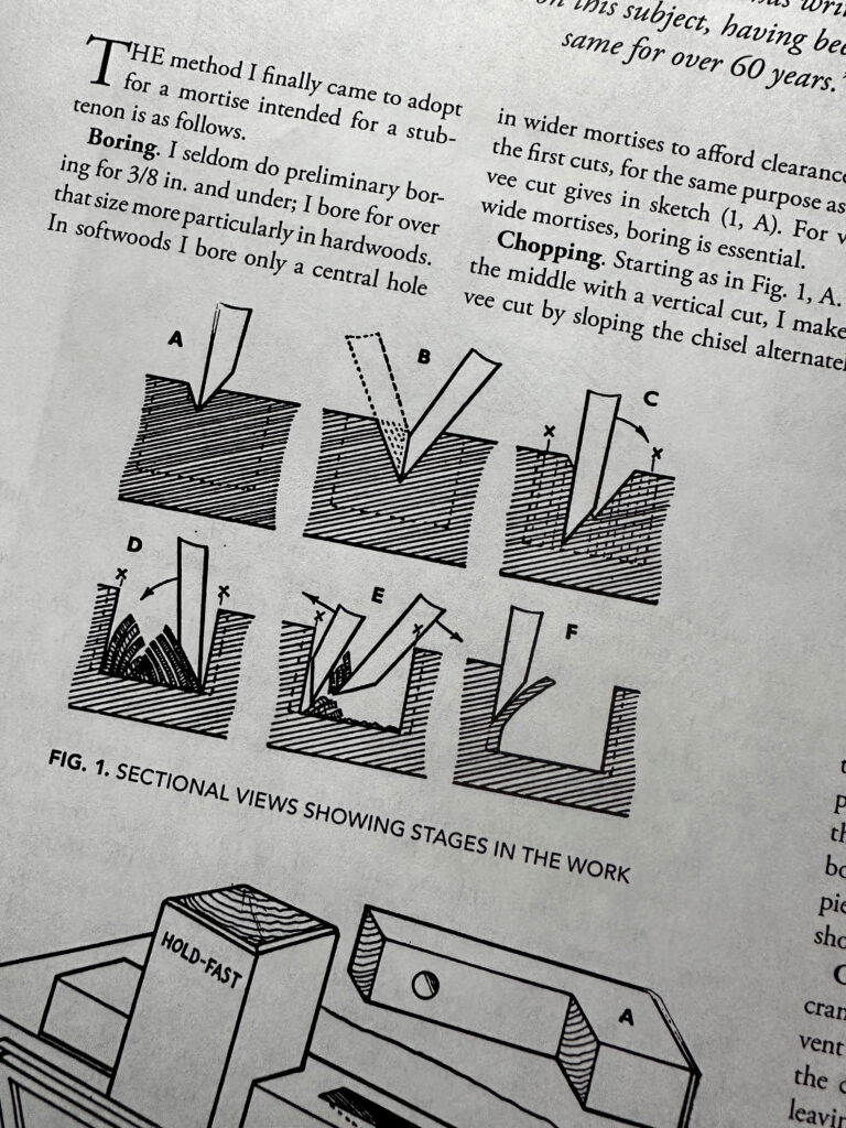
“The Woodworker” is filled with solid gold, such as this description of mortising. The best way (in my book).
This week I’ve signed off on a new press run of our four-volume set of “The Woodworker: The Charles H. Hayward Years.” We ran out of stock last year, and reprinting the books became prohibitively expensive (thanks, inflation!). I didn’t want to charge people more than $200 for these foundational texts on handwork.
So we worked with our printer to come out with a new four-volume set at an affordable price. What did we change? Only the cover. These books will be softcover instead of hardcover. The text will be printed on the same #60 paper. The pages will still be gathered into signatures and sewn for durability. The book will still be printed on offset printing presses in Michigan – not some digital perfect-bound piece of impermanence.
The four books will be wrapped in #100 Mohawk Carnival, a gorgeous American-made paper, for the covers. And we’re going to have a special introductory offer. Here’s how the pricing will work:
The set of four should retail for $139. But for the first 30 days, you can buy the full set for $100 with free shipping.
These books make me hyperbole. We spent eight years culling these articles from hundreds of issues of the now-defunct magazine The Woodworker. These books cover all aspects of handwork, from getting started to making complex mouldings and curved barred-light doors. By hand.
The 1,500 pages of proofs I reviewed to get these books back in print.
These books are densely packed with thousands of hand drawings by Hayward. The four books comprise more than 1,500 pages of information. All organized so you can find it (here’s a list of the entries). I consider these books to be the backbone of my handwork library. When I have a question about a technique or a tool, these books are the first place I look.
We hope to have all four volumes in stock by the end of February. Save your pennies. These books are worth it.
Note: The above image is unrelated to the column below – but we needed some illustration! It’s from Vol. 3 of “The Woodworker: The Charles H. Hayward Years.” That volume, along with the three other volumes that are currently out of stock, will be available again soon!
The following is excerpted from “Honest Labour: The Charles H. Hayward Years” – a collection of essays from The Woodworker magazine while the legendary Charles H. Hayward was editor (1936-1966). These columns are like nothing we’ve ever read in a woodworking magazine. They are filled with poetry, historical characters and observations on nature. And yet they all speak to our work at the bench, providing us a place and a reason to exist in modern society.
It always gives one a little sense of shock, I think, to come up against fresh evidence of what a very ancient craft woodwork is, and how very slow to change. During the re-building of the Bank of England, which took place a short time ago, workmen excavating the foundations came down to the peat bed of the old Walbrook, a stream which once ran right through the heart of the City, and in it they found an old Roman barrel in a remarkable state of preservation. This barrel is now on exhibition in the British Museum, in the gallery devoted to Roman remains in Britain, and is a magnificent example of how traditional craftsmanship has a continuity of its own. The metal bands have perished, leaving only a faint discoloration behind showing their position, but the wood itself is in a remarkable state of preservation, thanks to the action of the peat. And it shows in a startling degree how very little cooperage has changed in the last fifteen hundred years. There is the same treatment of the wood, with diagonal scraping over the inner side, the same bevelling of the timber edges. I nearly said the same bung-hole, but in this instance there are two bung-holes, the theory being that one bung may have got too tightly wedged in, and it was easier to make another hole than to force it.
To me there is always a thrill in discoveries such as these. They leap over the barriers of time, language and race—though even our word “cooper” comes from the Latin cuparius—and show us the men themselves, facing the same difficulties and overcoming them in much the same way as we do to this day. Man’s conquest of material was extraordinarily effective even in the ancient civilisations, and at the highest point of development in the civilisations of Greece and Rome was in no whit behind our own. If we want to see, for example, what the Greeks could do with stone, we have only to look at the Elgin marbles in the British Museum and see (broken fragments though they are) how they are penetrated with life and feeling; or to look at the marvellous Winged Victory of Samothrace in the Louvre to see how life and movement at their loveliest were wrought into stone, so that we are no longer conscious of it as a stubborn, inert material. Nowadays, by the development of machinery, we have discovered quicker methods for the handling of material, making large scale production possible, but we have carried creative art no further, because that is something which has its genesis in the spirit of man and not in his tools.
I wonder if we are not rather too content nowadays to leave creation alone. Even to let our woodwork confine itself to a few repair jobs about the house, a few useful labour saving articles, and not to set ourselves to conquer our material in real earnest and become expert craftsmen. We are not even dealing with a dead thing. Wood is a living, sympathetic material, having none of the stubbornness of stone; it is man’s oldest friend, and capable of giving beauty as well as service. A good many of us, I think, have the urge for achievement: what is really lacking is the faith to persevere, a faith which becomes increasingly difficult in a world where so little is done by hand. The older type of craftsman saw men all around him working in the same way: he knew what could be done and took it all for granted. But nowadays nothing is easier for the man who works with hand tools to develop a kind of inferiority complex and doubt his own powers, especially if he is doing the thing as a hobby and is out of touch with fellow workers. We need to remind ourselves not only of what is possible but of what other men have done; that a real flame of enthusiasm, combined with determination to become skilled, will liberate powers of doing and creating of which we can only be dimly conscious while we are content to potter.
For there is a dynamic quality about enthusiasm which nothing can resist. You can see it in the street orator, whose whole heart is in his argument, swaying a crowd. You can feel it in the work of any artist—painter, writer, musician, or whatever he be—if he has put himself into the thing he has wrought in, felt it enough, suffered it enough. And the beginning of the year is a good time, it seems to me, to set about enkindling our enthusiasm afresh. For life is a dead thing without it. Make it woodwork, if our tastes lie in that direction; make it stamp collecting; make it anything in the wide world so long as it is alive and vital.
Living as we have all been living, first in a war-weary world and then in a world distracted by slumps and war rumours, it has not been altogether easy to keep any enthusiasm alive. All the more reason then for renewal when the year begins afresh. And we can remind ourselves that some of the best work of the world has been executed in turbulent times. We can see it in the pages of old Vasari, the painter of the Italian Renaissance who has come down to fame, not by reason of his own pictures, but from the fascinating record he has left us of the Florentine craftsmen—mostly painters and sculptors—of the period. It has long been a habit of mine, whenever I want real refreshment of the spirit or feel that I want to recapture the spirit of enthusiasm, to turn back into the pages of old Vasari and read just how those men worked, with a fire, a zeal, a soaring ambition which has never since been equalled. It is a mine of good stories and sage maxims, and the men with all their oddities and idiosyncracies are made to live again. In Florence enthusiasm was communicated from one man to another to a marvellous degree. It is quaintly summed up in the words of an old painter to the young Perugino, who asked him why it was that in Florence men became so perfect in all the arts. It was because, he said, in Florence there was such a spirit of criticism abroad that men judged work upon its own good qualities rather than from the name of its authors. Then prices were so high that they spurred a man on to make money; and thirdly, the very air generated a thirst for honour and glory, since no man of ability would suffer himself to be outdistanced by other men “fashioned like himself, even though acknowledged to be masters.” Which gets to the root of the matter pretty thoroughly!
Fig. 2. China cabinet door, late eighteenth century.
As a general classification some six general types of doors have been evolved over the years, though the variations on each are almost unlimited. Only a few can be illustrated here, but the reader should find the range useful when he comes to design or make up a piece of furniture.
The purpose of a door is clear and obvious enough, yet the variety of ways in which it has been made over the years is amazing. Consider, for instance, how far removed the delicate-traceried door in Fig. 2 is from the single slab oak door in Fig. 1, virile and spirited though the latter is. Of course, the two belong not only to different ages, but also to different techniques of construction. Obviously, too, the usage the two would have to face would be entirely different, the Gothic specimen standing up to everyday use, whereas the eighteenth-century door belongs to a cabinet intended for a drawing room, used only by genteel people.
Framed and panelled door. Second half seventeenth century. Shows several interesting features. The stiles are beaded with the scratch stock, but the beads run out at the rails so that the tenons have square shoulders. On the centre muntin no attempt is made at mitreing—indeed, there is no corresponding moulding on either rail. The difficulty is overcome by butting at the top and scribing.
At the outset it is interesting to consider the reasons for changes in construction, apart from the variations in form largely dictated by fashion. A single slab of wood is the simplest form but carries with it certain disadvantages, perhaps the chief of which is its liability to shrink. It might also cast, though both of these potential faults would be minimised by the use of quarter-cut timber. Possibly a more serious drawback is the limitation imposed by the widths in which timber is available. A wide door would have necessitated jointing and possibly using cross-battens at the back. A last undesirable feature is the single grain direction. Oak is a tough wood, but it does cleave easily, and such a door could easily break.
Framed door with turned spindles. First half seventeenth century. Frame is joined with mortice and tenon joints, the spindles having dowels turned at the ends. Turning appears to have been introduced in the mid sixteenth century and was quite commonplace in the following century. Most early turning was done on the pole lathe, the springy pole reversing the rotation after the power stroke.
It was no doubt a combination of these drawbacks that brought about the framed system of construction. The frame itself provided strength across width as well as height, the panel being more or less a filling. Being free to move in its grooves, there was no liability to split in the event of shrinkage, and the over-all width of the door could be increased—in fact it only needed centre muntins for the width to be increased ad lib.
Single slab oak door. First half sixteenth century. Pierced right through with Gothic tracery designs and with simple channelled moulding cut with the gouge. From a food cupboard. It is in a single piece of oak, and has suffered from woodworm, but is otherwise sound and has remained quite flat. It is the simplest form of door, but has certain constructional disadvantages (see photo [at top]).
The introduction of veneering made it desirable to have flush surfaces, and so the clamped and flush panelled door was used, not always with success owing to its liability to split due to resistance to shrinkage. Finally today we have veneered flush doors of multi-ply, lamin-board, or chipboard, in which many faults have been eliminated (though even here there are certain snags).
Framed and panelled oak door. Early seventeenth century. The craftsman has used the true mitre, and has overcome the problem of combining this with the grooving to contain the panels. Note how the mortice is set in at the inside since the tenon is automatically cut away by the grooving. At the same time the tenon has long-and-short shoulders because the front of the stile has to be cut back level with the moulding which is worked in the solid. The whole thing is assembled without glue, the joints being pegged. Mostly the oak was quarter-cut, sometimes being riven.
Framed door with raised panel. Second half seventeenth century. The main outer frame is grooved to hold the panels, but the moulding is separate and is mitred round. At the centre the main members are mitred and rebated to take the small raised panel, a bolection moulding being fitted to hold it. Sometimes quite elaborate patterns with mitred mouldings were made. One common pattern had diamond-shaped panels, in which case, of course, the mitre lines halved the over-all joining angle. Bolection mouldings giving a raised-panel effect were often used.
Flemish cabinet door. Seventeenth century. The moulding of the main framework is worked in the solid and is mitred at the corners. A characteristic feature is the wide use of channelling and flat recessed beads. Carving is in the solid, the background being cut back leaving the detail in shallow relief.
Long clockcase flush door. Late seventeenth century. Interesting in that it is an early example of veneering. The ends are clamped as shown and a strange feature is that the clamps are sometimes merely butted without any tongue. It seems a risky construction, but of course the veneer strengthens it considerably.
Clamped and veneered flush door. Second half of seventeenth century onwards. Most usual construction was of pine with clamped ends tongued on. The weakness was the liability of the main panel to shrink, and this showed itself eventually either in stress marks in the veneer towards the edges as shown here, or in cracks towards the centre. An alternative sometimes followed was to fit a flush panel in a framework, but there was still the potential danger of cracks or stress marks due to shrinkage.
Framed and veneered door. Early eighteenth century. Framework is veneered with walnut, and has an applied bolection moulding at the inner edge forming a rebate for the panel. Construction is rather unusual in that the top rail runs right through, and has resulted in slight stress marks, the consequence of shrinkage. The veneer is mitred at the corners, but was frequently butted, the joint lines vertical.
Barred door in mahogany. Mid-eighteenth century. The lattice moulding was usually of astragal section about 3/8 in. wide, the back grooved to fit over 1/8 in. bars. The glass was either beaded or puttied in. Note that the section of framework moulding is half that of the lattice. In all cases the mitre lines halve the over-all angle of the joining mouldings. Below are framework and moulding sections.
Framed door with fielded panel. Mid-eighteenth century. A costly door to make, especially by hand methods. A square-edged frame would be made first, and the inner shape bow sawn. The rebate would be largely chiselled. The scratch stock would be used for the moulding, though the carver would finish off the sharp inner corners. The fielding of the panel would again need the scratch stock.
Panelled and veneered door. Second half eighteenth century. Made in either of the two ways shown. The frame is assembled and the elliptical shape cut out. After veneering across the grain the small thumb mould is bent round and fixed, thus forming a rebate. The panel is veneered, dropped in from the back, and held with a bead.
Framed and panelled door. About 1770. The top curve is formed by making the top rail extra wide and packing the stiles locally, cutting to shape afterwards and veneering. The moulding would be either made up separately and applied, or worked in the solid. In the latter case the whole thing would have to be in mahogany, or a local edging of mahogany would be applied. Lower quadrant corners are set in separately.
Built-out door in mahogany. Second half eighteenth century. Here again the top is a wide rail cut to shape after assembling. The rebate is worked around the curve (that on the straight parts being done before gluing up). The panel is dropped in flush and the joint covered by a half-round sausage and berry mould. Tongues are used to hold the canted corners.
French type door, part gilt. Late eighteenth century. Rails are made wide enough to include the curves, and are put together with long-and-short shouldered joints, the stiles being rebated beforehand. After cutting the rails to shape the rebates are continued round the curves. The panels are dropped in and held by the face moulding which is mitred round. To form the carved details blocks are glued on and carved when in position, though in some cases the whole thing is carved in the solid, the groundwork being recessed.
Barred door in mahogany. Late eighteenth century. After assembling the framework, the bar mouldings are grooved and worked with the scratch stock at the shaped edge of a board, cut out, and assembled over a marked-out panel fitted to the door rebate. All mitre lines halve the over-all angle. Glazing bars are added at the back afterwards, being checked into the frame. Thin strong canvas glued to the joints in the bars strengthens them.
Framed door with raised panel. Early twentieth century. The framework is morticed and tenoned together, the inner edges being grooved to receive the tongues of the panel. The latter is grooved to enable the panel to project, and a wide rebate on the face gives a double stepped effect. The tenon is haunched, the end of the groove being thus filled in.
Raised and veneered door. About 1930. Here again the panel is raised and is tongued into the framework which is mitred and tongued. A wide, shallow chamfer is worked around the framework before assembly, and a corresponding local chamfer formed at each corner (see dotted lines). The panel corners are canted to line up with the chamfers.
Veneered flush door. Late eighteenth century onwards. Narrow straight-grained strips are glued side by side with heart sides alternately outwards and inwards. In best work this is counter-veneered across the grain both sides, and the face veneers put down lastly. In many ways this is the most reliable construction. Counter-veneers are frequently omitted, even in good class work.
Gothic oak door. Modern construction. The main framework is grooved to hold the panel, and the mould at the edge is stuck in the solid, the corners being finished with the mason’s mitre. To obviate extensive recessing, the tracery is applied, the whole fitting into the grooves in the framework. To avoid shrinkage complications the grain of the tracery is vertical and thus any movement in this is the same as that of the panel. Note that the groove in the framework is wide enough to take both panel and applied tracery.
Veneered flush door. Modern style. Both sides of the door should be veneered, and in the best work both sides are counter-veneered. Note that in any case the grain of the veneer which touches the groundwork is at right angles with the outer layer of the ply or laminboard. Unless this is done hair cracks may develop. Usually such a door has to be lipped. If this is done first it is concealed by the veneer. When done after veneering it shows but protects the edges of the veneer.
Framed and faced door. Modern. Usually the framework is dowelled and panels of plywood or hard board glued on, preferably on both sides. When the door is large it is advisable to bore holes through the framework so that the air contained in the spaces remains at equilibrium with the outside atmosphere. Such doors are usually used for kitchen fitments, etc., and are intended to be painted. The intermediate rails are desirable because otherwise the panels are liable to sink locally.
Folding-sliding doors. Modern. Invariably the flush-type door is used, the three members being hinged together as shown. Pivots are fixed top and bottom at the edge of the centre door, these sliding in grooves in the top and bottom. As it is difficult to fit the pivots at the extreme edge of the door, the width of the latter needs to be calculated carefully so that when opened fully it lies back flat with the door hinged to the cabinet side. The doors nowadays are usually veneered plywood or blockboard, in which case they are lipped.
Frameless sliding glass door. Modern. Although the glass can slide in grooves worked in the wood, it is more usual nowadays to use the special metal or plastic channelling made for the purpose—at any rate at the bottom. It is essential that the top grooves are double the depth of those below so that the doors can be lifted out.
Framed sliding door. Mostly twentieth century. Here modern practice is to use gliders beneath the door, these running on special fibre track. Bottom edge of door is grooved, but track does not engage with this. It is made to take the gliders and at the same time give clearance over the track. Top of door may slide in wide groove.
Bow-front door. Eighteenth century and onwards. Framework is rebated and moulded to receive the panel, an essential feature being that the stile rebates are parallel so that the panel can be inserted after assembly. Owing to the short grain of the rails, it is more satisfactory to use dowels than tenons as the last named would have little strength. An alternative is to fit loose tenons.
Serpentine doors. Eighteenth century and onwards. Here again the rebates have to be set out so that they are parallel, but usually there is no difficulty because the curves often cancel each other out. When curvature is only slight the panels are usually bent. Today all rebates and mouldings would be worked on the spindle moulder or with the electric router. For hand work the rebates would be part planed and part gouged and chiselled. For the mouldings the scratch stock would be used.
Bow flush door. Eighteenth century and onwards. Traditional construction was to cooper the doors and veneer both sides, preferably counter-veneering as shown. Present-day tendency is to laminate, gluing the layers between pairs of formers. The face veneer could be made up separately and put down with a curved caul, though care would have to be taken to ensure that the mitre lines coincide with the corners. Otherwise the centre panel could be laid, and the elliptical shape cut round the edge of a templet. Afterwards, the border is fitted up to it. To avoid a bad joint it is common to fit an inlay line round the edge of the ellipse.
French bombe door. Mostly eighteenth century. Expensive doors owing to the compound curvature. Setting out in both plan and elevation essential. By jointing pieces together and adapting their width according to their position, it is only necessary to level the joints to reveal the line at the fulness. At top and bottom a templet is used to show the shape. Some such procedure is essential as the doors are always made in pairs, and the two must obviously be alike. At the meeting edge another templet is used to mark the shape, but the blending of the curves becomes a matter of judgment. The work on each should be done in stages, and the two placed together in position for the final shaping. Parallel lines drawn horizontally enable further testing templets to be used in various positions, but the hand drawn lightly over the surface reveals any waviness. Veneering both sides follows, and invariably a built-up pattern is used to enable the veneer to be tailored to the curve. Reliable straight-grained wood is essential for the groundwork.
Tambour doors. Eighteenth century onwards. Consists of a series of narrow strips glued to canvas backing. Ends fit in grooves worked in top and bottom. As most tambours bend in one direction only it is necessary to cut a feeding channel at the back as shown by the dotted line, this being afterwards filled in. Strips may be of the same wood or in contrasting woods. In the former case they are often cut from a single board and assembled in same order, When a flat section is used (V), the joints are almost invisible. Narrow-bead sections may be worked in pairs (W), but wider ones need to be worked singly (X). When bending in both directions is necessary a similar section to either (Y) or (Z) is necessary, though only slight reverse bending is possible. This curvature is sometimes needed on serpentine shapes. It is necessary to assemble the strips on a jig as it is essential that they are put together square, otherwise curious complications can arise. For a bow-front cabinet the assembling jig would have to be correspondingly curved.
Chief types of doors. We show here in simplified form the main types, with all decorations and complications omitted. All doors are based on one of these, or combinations of them. 1. Slab or solid type. Has the advantage of simplicity but has some drawbacks such as liability to cast and to shrink leaving gap at closing edge. 2. Framed and panelled. Panel may be grooved or rebated in. Latter preferable for work to be french polished. Edge may be moulded or moulding may be applied. 3. Clamped. Suitable for flush, narrow doors only, and wood must be well seasoned. A combination of this and No. 2 is the framed and flush panelled type, the panel being tongued in and finishing level at the front. 4. Flush. Of laminboard or multi-ply. For polished work it is veneered both sides. Lipping may be added and an extra wide lipping fixed one side to take hinge screws. 5. Framed and faced. Used mainly for painted work. 6. Tambour. Useful alternatives for a wide, shallow space; also when hingeing would be impracticable.
1) The Workshop, including the design and construction of workbenches, tool chests and wall cabinets. There’s also an entire section devoted to “appliances,”which are workshop accessories such as shooting boards.
2) Furniture & its Details, includes a discussion of all the important Western furniture styles, including their construction, mouldings and metal hardware. This section also includes the construction drawings for many important and famous pieces of furniture examined by Charles H. Hayward during his tenure at The Woodworker magazine.
3) Odds & Sods. In addition to offering its readers practical information for the shop, The Woodworker also asked it subscribers to think about the craft and its place in modern society. We have included many of our favorite philosophical pieces in this final section.
Although a back may not call for the high finish that is necessary for, say, a cabinet door, it needs to be strongly made and of a type to suit the particular job. “Craftsman” discusses here some of the points to be considered when deciding just what kind of back a job is to have. —Ed.
I am afraid that many of us are inclined to let the backs of our cabinets take pot luck, as the saying goes. We make a job, say, in oak, possibly putting in oak drawer sides, and backs, but hesitate before going to the expense of oak for the back. The reason (or excuse, however you happen to look at it) is that it is seldom seen, has little or no wear to withstand, and that, since the cheap back answers the purpose just as well, it is clearly a waste to spend money on an expensive one.
Well, it is logical enough up to a point, and, providing that it is merely the material that is cheapened and not the method that is worsened, no great harm is done. In fact, there are many pieces of quite light woodwork in which a heavily built back seems almost out of place. Still, it is nice to have a piece of work in which nothing has been skimped, and the argument that a cheap back answers the purpose as well as a better one may not necessarily hold good, as we shall see later. The safe plan is to consider each piece on its merits, and give it the best back that it is worth.
BACKS OF OLD FURNITURE If one goes back into the past one comes across some curious anomalies. Many of the antiques of the Queen Anne and mahogany periods of which we think so highly had wretched backs. I myself spent a good many years in a repair shop, and I can speak feelingly of the hours I devoted to gluing strips of canvas across gaping splits in panels and across open knot holes. I have seen a mahogany chest of drawers of the Chippendale period with magnificent show work—serpentine shaped drawers, fine carving, and so on—with a back consisting of pieces of 1/4 in. pine nailed across. An extraordinary inconsistency. Apart from its having no strength, the whole thing was bound to shrink and split.
Yet when we come to that much abused period of Victoria, we find exactly the reverse. Probably no finer cabinet backs have ever been fitted into furniture. Open the door of one of those huge Victorian wardrobes (there are plenty of them knocking about in seaside boarding houses). You will find the mirror back more strongly made than many a modern wardrobe door, and the carcase back a finely panelled framework often with moulded stiles or flush panels.
Perhaps one reason why there has been a tendency to fit lighter backs since Victorian times (apart from the all-round cheapening of materials and construction) is the introduction of plywood. It seems such an obvious use for ply, a material which is free from shrinkage and obtainable in such large sizes. Undoubtedly it is perfectly suitable for the purpose, providing the carcase is strong in itself, and does not rely upon the back to make it rigid.
TYPES OF BACKS There are various considerations that affect the choice of a cabinet back. There is, for instance, the question of size. A single sheet of 3/16 in. plywood might make an excellent back for a little cupboard, say, 15 ins. high, but would obviously be absurd for a wardrobe. Apart from this, however, the first consideration should be: does the job rely upon the back for strength, or will the back serve merely to enclose a space? Fig. 1 shows the idea. At A the back is needed to prevent racketing and to stiffen the carcase generally. At B, however, the carcase is already strong, and only a light back is needed.
In the latter connection, of course, it is sometimes an advantage to build in the back with the carcase. Items such as sideboards are often made in this way. As a general rule, however, it is better to make the back separately, because it simplifies the subsequent fitting-up.
THE PANELLED BACK For a thoroughly strong back the panelled type is undoubtedly the most satisfactory. It is perfectly rigid and is free from all shrinkage complications. It should always be used for pieces such as cupboards with large, heavy doors, which are particularly liable to distortion unless provided with a stiff back.
Fig 2 shows the usual form. The whole thing is put together with mortise and tenon joints, and the panels are grooved in. One point to note is that if there is a shelf in the cupboard, the middle cross rail should be arranged opposite to it if possible. It may not always be practicable, of course, but the advantage is that it gives a level surface against which the back of the shelf can face (see B, Fig 3). If this is not done there will be gaps opposite the panels as shown at A.
The same difficulty sometimes occurs in a bookcase or similar item, but owing to the large number of shelves it is not practicable to arrange for many horizontal rails. The better plan is that in Fig 4, in which the panels are flush with the framework at the inside. It necessitates fairly thick panels, of course, but it gives a far neater result than cutting out the back edge of the shelf to fit.
MUNTIN BACKS A somewhat distant relative of the panelled back is the muntin type. It is nowhere near as strong, and is rather a doubtful member of the family. Like some relations, you can’t deny them (and they are useful sometimes), but you are a little shy about mentioning them in the best circles. It consists of a series of uprights, say 3/4 in. or 7/8 in. thick grooved at the edges to take thinner panels, as shown in Fig. 5. The ends of the muntins are cut away as shown inset, so that the panels can be fixed directly to the back of the carcase. Now, as the panels are generally about 9—10 ins. wide, and of deal, it is inevitable that a certain amount of shrinkage will take place. Consequently it is a mistake to drive in nails right across the width because the wood would split in the event of shrinkage. The better plan is that in Fig. 6 in which nails are driven in near the centre only. The edges extending into the muntin grooves are free so that they can draw out. Note that the heart side is outwards so that the free ends are pressed tightly against the carcase by the natural twisting tendency of the wood.
If, owing to the presence of a number of shelves, it is desirable for the back to be entirely flush on the inside, the muntins can be rebated instead of grooved as shown in Fig. 7. The beads along the rebates are not entirely decorative, but they serve to render the gaps less noticeable in the event of the panels shrinking. All these details about shrinkage apply only when solid wood is used, of course. In the case of plywood it does not matter.
Speaking of plywood brings us to another variation of the muntin back. In its simplest form the plywood back is nothing more than a sheet of plywood nailed or screwed in a rebate. For quite light jobs this is satisfactory enough, but to give a neat finish the back in Fig. 8 is better. A series of grooved and rounded horizontals is screwed on. They can be arranged level with the shelves as shown. The plywood panels fit between them in the grooves. For a flush effect the rails can be rebated instead of being grooved (see D).
FIG. 9. DRESSER BACK WITH TONGUED BOARDS FIXED DIRECTLY TO CARCASE.
DRESSER BACKS These are really in a class by themselves, for although they could be applied to pieces such as wardrobes, they are not so strong as a panelled back. One of two methods can be followed. That shown in Fig. 9 has the advantage of simplicity. The back is really a series of matched boards, tongued one into the other, with either a bead or a V worked at the joints. The boards are screwed or nailed directly to the top and shelves, and at the bottom to a rail specially fitted for the purpose. In the second method, Fig. 10, wide grooved rails are screwed at top and bottom and the matching fitted in the grooves. The wide rails give rigidity, the matching merely filling the space, so to speak. It can be either very thin as at A, or it can be stouter, the ends being tongued as at B.
FIG. 10. DRESSER BACK WITH TONGUED BOARD FITTING IN GROOVED RAILS.
Incidentally, a detail applying to all backs of any thickness is that the rebates in the ends should slope as shown at A, Fig. 11. If this is not done the projecting portion is liable to curl as shown at B.
FIG. 11. DETAIL APPLYING TO ALL BACKS. At A the rebate is cut at an angle. This avoids risk of the projecting lap curling away as shown at B.