This is an excerpt from “The Woodworker: The Charles H. Hayward Years: Volume II” published by Lost Art Press
One of the perplexing questions which the cabinet maker appears to have never settled definitely is: should drawer fronts stand out slightly in front of the carcase and the bearers, or should they stand back with a slight break? Here are a few notes which may assist readers in deciding the question.
At Fig. 1 the drawer projects beyond the bearers and at the same time forms a rebate or lap around the drawer proper which is more or less dustproof. In cheap work the projecting front is applied, in which case the drawer is through dovetailed at each corner and, when completed and run into position, the 3/8 in. or 1/2 in. front piece is applied and glued in position. If shrinkage occurs in the drawer boxing, the applied piece hides the joint owing to its overlap.
There is, however, likely to be one defect when the drawer is open. Owing to atmospheric changes, and the continual opening and shutting, the polished front edges of the bearers are apt to become marked by the overlapping portion of the drawer front (see arrow).
At Fig. 2 the drawer front stands in about 3/32 in., and this method is the one most generally used. The usual trouble with this type is that the polisher neglects to fill in, stain and polish the inside edges of the bearers and carcase ends to the same degree of efficiency as the drawer fronts, etc. (see arrow). The result is that the continued use of the drawer quickly wears away the polish on the break and the job appears shabby.
The moulding around the drawer front is worked in a variety of shapes and the drawer front has the appearance of a fielded panel. If the face of this fielded panel happens to be veneered there is very little fear that the edges of the veneer will chip away, because it does not come in contact with the bearers.
If the drawer front has square edges and is not fielded, the veneer is liable to chip at the edges which come in contact with the bearers.
Fig. 3 is a very successful method for drawer fronts. Here the drawer front stands 1/16 in. to 1/8 in. forward and the break (see arrow) on the drawer front does not rub against the bearers or the carcase end. The polisher rarely neglects to obtain a good finish on this top edge of the drawer (which usually carries the lock) and when filling in and staining the front of the drawer sufficient material creeps over the ends of the front to ensure a decent finish on the end grain. This appears to be a fairly satisfactory method and the edge of the polished drawer front is not worn away by the continued opening and closing action. The idea, of course, works out the same even if the drawer front is a square edged one; that is, without any moulding around it.

At Fig. 4 we come to what is probably the oldest and best method of protecting a veneered drawer front. This is known as the cocked bead method and is frequently found on Queen Anne furniture. Around the drawer front a rebate is formed and into this the beads (C) are glued. In some cases they are also pinned. The beads have one rounded edge and are mitred at each corner. The projection when polished is not defaced by friction and the edges of the veneered front do not come in contact with the bearers or the carcase ends during the travel of the drawer.

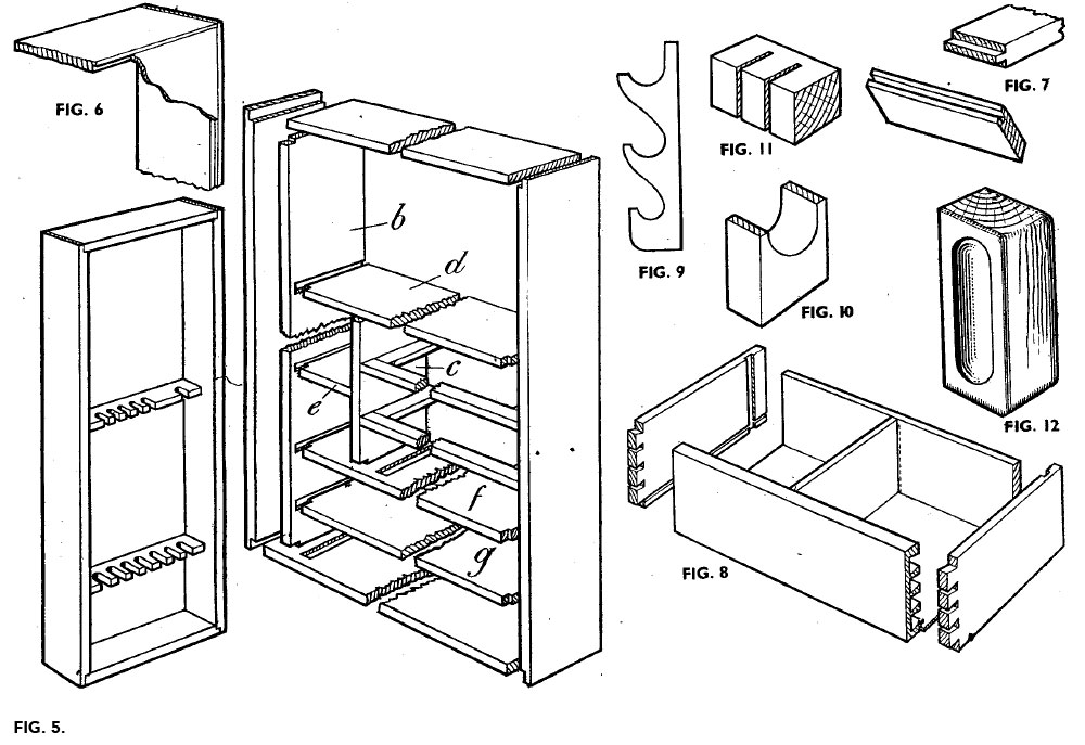
A somewhat unusual method is given at Fig. 5. It is costly to produce and calls for very fine craftsmanship. The edges of the bearers and the inside edges of the carcase ends have a mould worked upon them. The bearers are twin-tenoned into the ends (see Fig. 6) and all the moulded edges are mitred together. Thus we have the mouldings worked upon the solid portions of the carcase and bearers instead of working the moulding on to the drawer fronts. The drawer front usually forms a break with the mouldings by an inset of 1/16 in.
Drawer fronts may be stopped in their required positions by fixing two rectangular pieces about 1/8 in. thick immediately behind the lower edge of the drawer front; or they may be stopped by fixing suitable pieces of wood to engage the back ends of the drawer sides. In either case the worker should arrange the stops so that no shrinkage will take place.
— Meghan B.