This is an excerpt from “With all the Precision Possible: Roubo on Furniture.” It is a follow-up to the post from a couple weeks ago that described a “machine for making waves.” Below is a portion of an essay by Jonathan Thornton that was written after he made one of these machines based off of historical descriptions of the machine.
The book “With All the Precision Possible: Roubo on Furniture” is the result of more than a decade of work by an international team that produced the first English translation of the 18th-century woodworking masterpiece: “l’art du Menuisier” by André-Jacob Roubo. This translation covers Roubo’s writing on woodworking tools, the workshop, joinery and building furniture.
In addition to the translated text and color images from the original, “With All the Precision Possible: Roubo on Furniture” also includes five contemporary essays on Roubo’s writing by craftsmen Christopher Schwarz, Don Williams, Michael Mascelli, Philippe Lafargue and Jonathan Thornton.
Introduction
Anyone with longstanding interests in woodworking and the history and technology of picture frames could not help but be intrigued by the complex rippled mouldings that are most commonly seen surrounding paintings of the Baroque period. If that person is also a maker and collector of tools, as I am, then the construction of a device to make them is a strong temptation. It was years ago now that the temptation became almost an inevitability with my discovery of an engraving of such a device in Joseph Moxon’s seminal work on technology, “Mechanick Exercises.” 1 All I needed was the time, which was furnished by a semester sabbatical in 1994. I built a close reproduction of his device and have been exploring its capabilities as well as the literature on the subject ever since.
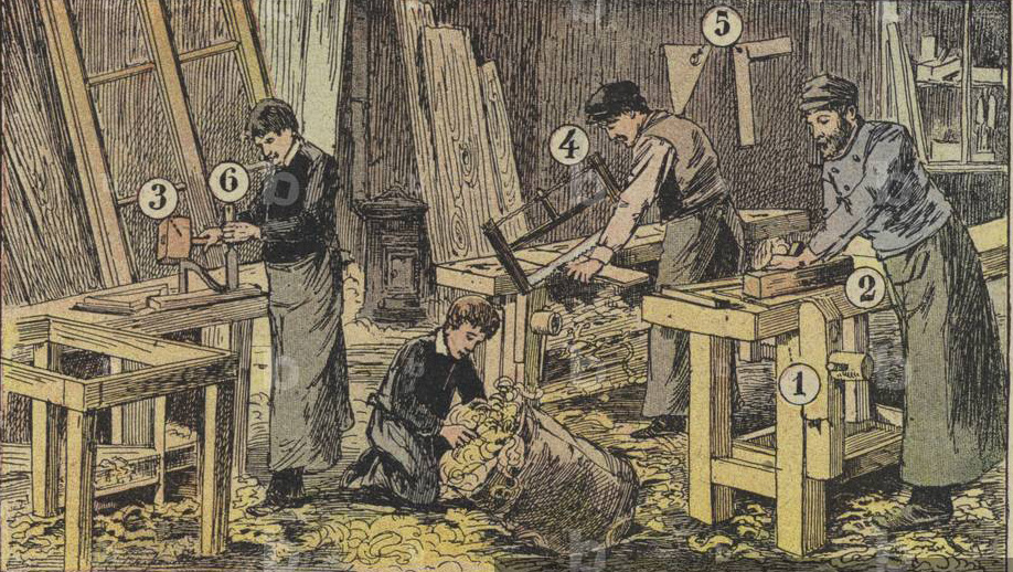
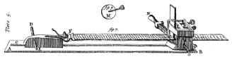
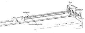
Moxon’s device intrigued me for several reasons: it was neglected or misunderstood in the available literature, it appeared that it would be capable of producing a variety of complex waveforms and it was the only type of such devices that to my knowledge had not been faithfully reproduced (although a somewhat modified version had been published in Fine Woodworking in 19862). The device, called the “Waving Engine” by Moxon (Fig. 5.1), works on a relatively simple principle. A stock piece is fastened to a guide or template rod carved into a waveform, and they are pulled together through a stationary cutter. As the guide rod rises and falls over a polished feeler bar, the waveform is gradually cut into the stock piece by a fixed blade. While the principle is simple, the devil is in the details.
Making the Machine
The illustration of the device that Moxon provides (from a plate almost certainly engraved by himself) presents a few problems of interpretation, and Moxon’s description, while fairly thorough, omits some important information. My intent was to make Moxon’s “engine” to his specifications, and if modifications had to be made, the reproduction itself would tell me what to do, and not my own second-guessing.
“The Waving Engine…hath a long square Plank…All along the length of this Plank, on the middle between the two sides, runs a Rabbet…Upon this Rabbet rides a Block with a Groove in its under side…the Groove in the Block is made fit to receive the Rabbet on the Plank.” (Joseph Moxon)
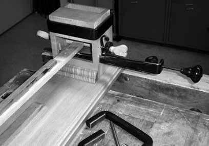
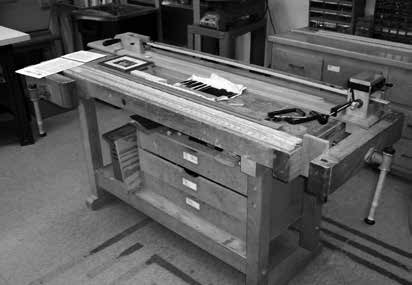
I made the plank from quartersawn sycamore. The rabbet I made from hard sugar maple, likewise the block that rides on it. This is the block that pulls both the patterned template and the stock piece through the cutterhead. Moxon attaches these elements to the block with a “Vice, somewhat larger than a great Handvice….” In considering this, I made the only major deviation from Moxon’s machine. I didn’t see how a fixed vice could easily follow the up-and-down motion of the guide rod (“rack”) and stock (“riglet”), let alone the gradual raising of these strips as the molding was cut. I suspect that simple looseness of fit allowed Moxon’s machine to accommodate these movements. In place of the hand-vice, I forged a tongue with a hinged box joint (mortise and tenon) much like the joint in a pair of pliers. The tongue would move to accommodate any adjustment upwards. The tongue itself was fastened into the block with a rod, which threads through it and also penetrates the block (at an angle — the purpose of which I will make clear). By means of this rod, I can adjust the attachment point to accommodate different widths of stock. In addition, I placed a support rod and knob under the end of the tongue and likewise threaded into the block, so that I could raise the attachment tongue correspondingly as the strips rose. This modification does not alter Moxon’s method in any important way, while making the machine easier to use.
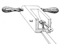
“At the farther end of the Plank is erected a square ∫trong piece of Wood…This square piece hath a square wide Morte∫s in it on the Top…upon the top of this is a strong square flat Iron Coller…”
This is the business end of Moxon’s device which I call the “cutterhead.” My upright block was made of a single piece of maple, with the appropriate mortises as described. I added two projecting through-tenons to fasten the block into the plank, so that they could be gripped by the end-Vise of my workbench when the machine was in use, and allow me to easily disassemble the machine when it was not. The purpose of the collar is to clamp the fixed scraper-type blade perpendicular to the stock piece. My collar was forged from mild steel, as were the screws that tighten it on the block. Like Moxon, I forged perforated disks on the ends of the screws, so that a bar could be inserted to tighten them with lever action. It is important that the blade not move while in use.
Moxon is at his sketchiest when it comes to how the depth of cut is gradually increased, although the engraving seems to show what the description omits. A bar is shown penetrating the block underneath the “rack” that appears to be both tapered and furnished with a threaded rod for gradually advancing it under the work. There can be no other way to do this in a controlled way. Jutzi and Ringger in their discussion of Moxon’s machine had a different interpretation.19 They speculate that this knob, projecting out of the far side of the machine, was used manually by a helper to lift the guide rod and workpiece against the blade. Moxon however, refers to this as “a wooden screw called a Knob.” He also appears to illustrate, though he does not discuss, the taper of the polished rod that is advanced by this screw-knob. It seemed clear to me what he intended: I made a steel bar with a T-shaped cross section that would slide through T-shaped slots in the block. I put the taper side up, as Moxon appears to do, and simply accounted for this cant in the rack and “riglet,” by setting my attachment-tongue into the pulling block at the same angle.
moulding on the Moxon “Waving Engine.”
I captured the end of my adjusting screw-rod with a sort of clutch lever that would allow me to easily disassemble the machine, an alteration necessitated by my own tight space that again, did not alter Moxon’s device in any important way. The screwrod uses a fine thread so that I can very gradually raise the work under the cutter. In use, one or two revolutions of a rosewood knob on the end of this screw increases the depth enough for the next cutting pull. The handles on my pulling block were also made of turned and polished rosewood, press-fitted onto a steel rod, which runs through the block, again for ease of knock-down.
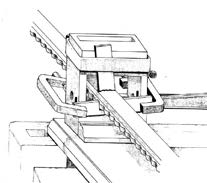
“But before you draw the Rack through the Engine, you must consider the Office…of the iron screw…for by these screws, and the Rabbet and Groove, your work will be evenly gaged all the way…under the edge of the iron.”
Moxon shows only one screw, though he refers to them in the plural. These screws serve to keep the work “gaged” under the blade. The end of the screw shown was fitted with a flat iron disk, that appears to be a sort of wear-plate against the moving template and workpiece, called the “rack” and “riglet” respectively by Moxon. Jutzi and Ringger speculate on two screws, one from each side, that enter at an angle. Their drawings are interpretive reconstructions as they did not build such a device.
I believe that Moxon clearly shows a screw entering perpendicular to the cutter-head block. I also decided to use two screws, so that I would have greater flexibility than could be achieved with just one, though the inside surface of the cutterhead could have conceivably gauged the other side of the strips. Instead of iron, I made my screws from lemon-wood (Calycophyllum candidissimum), a beautiful close grained relative of boxwood, and equally hard-wearing. I threaded these with the Beall router attachment, and made decorative double volute-shaped flanges on the ends similar to the screw end shown by Moxon. I decided that locking washers were a good idea if I wanted to keep my work well “gaged.” I made these from rosewood also, and placed them on the outside of my block where they are easier to get at.
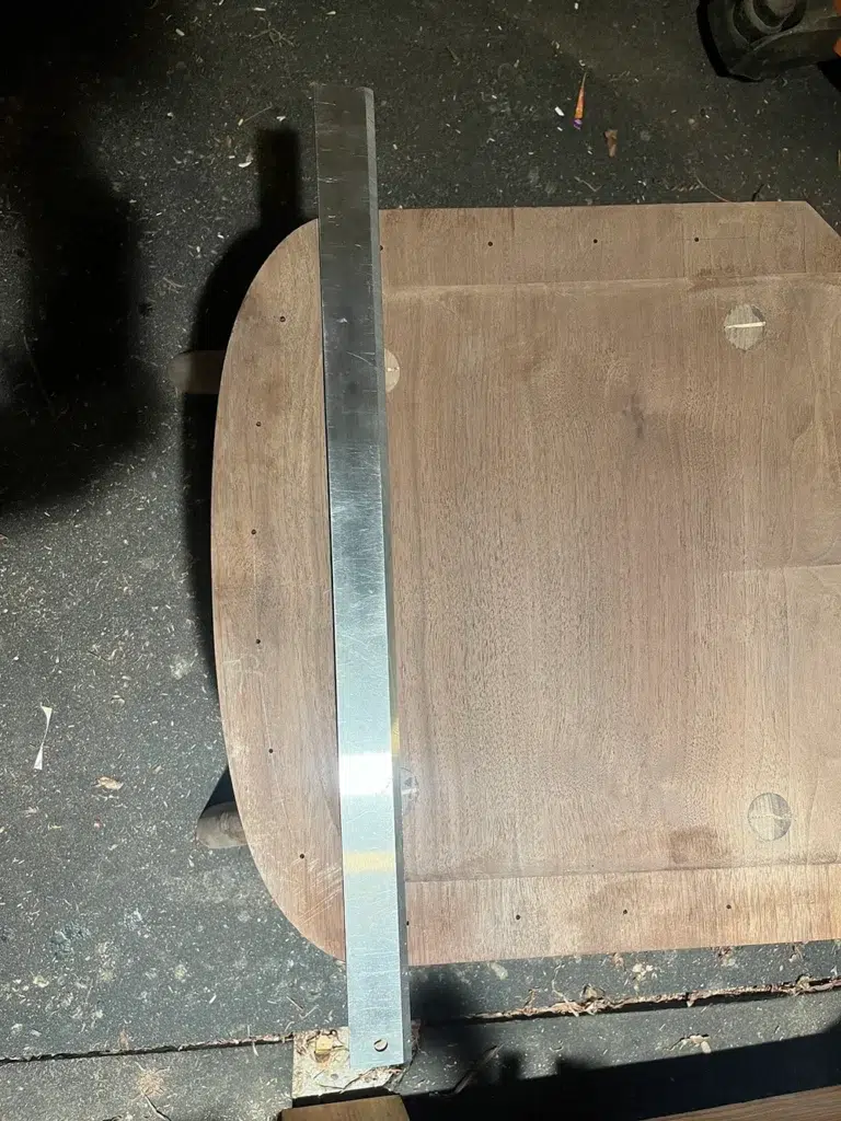
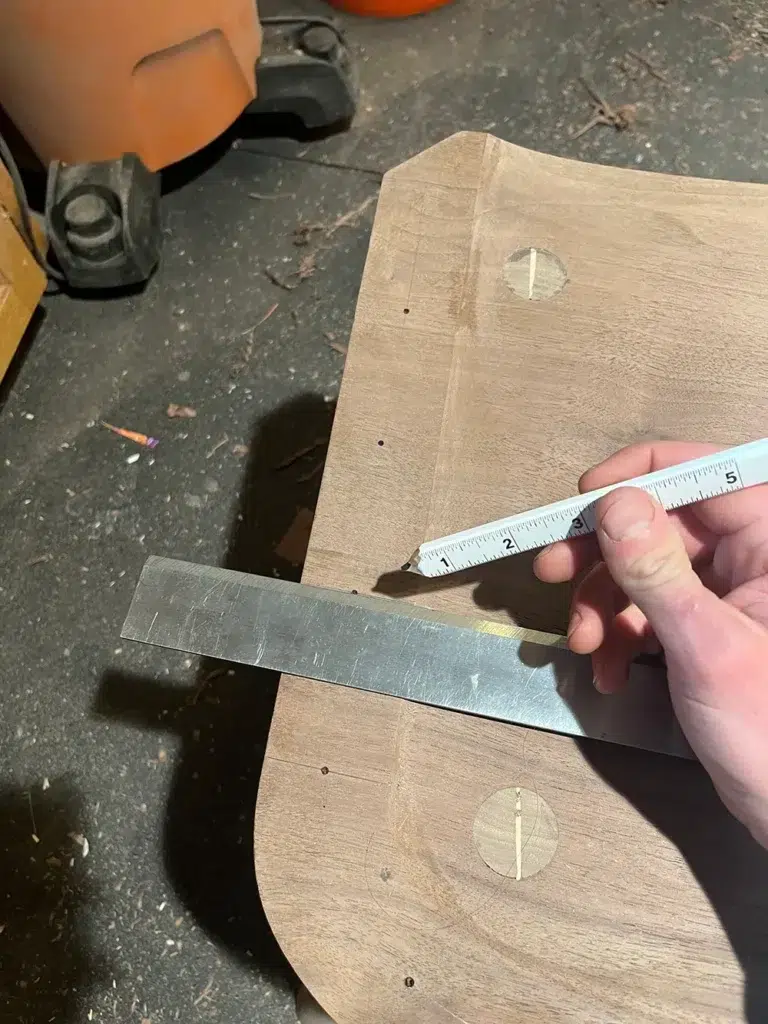
My blades were made from 01 steel, a high-carbon, oil-quenching tool-steel that has low warp characteristics in hardening, and can be tempered to create a tough and hard blade. The blade “whose lower end is cut into the form of the Molding you intend your work shall have…” has a single bevel facing toward the pulling block. I filed and ground the shapes before hardening the blades. I sharpened them once on the bevel, then subsequently only on the flat side.
“Then if you lay hold of the handles of the Block…and strongly draw upon them, the Rack and Riglet will both together slide through the Mouth of the wooden piece…and as the rounds of the Rack rid over the round edge of the flat iron…the Riglet will on its upper side receive the Form of the several Waves on the under side of the Rack, and also the Form, or Molding that is on the edge of the bottom of the iron, (blade) and so the Riglet will be both molded and waved.”
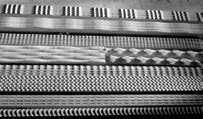
The final form of the mouldings is dictated by the shape of the blade, by the form of the template or combined templates, and by the attachment point of the pulling block. The number of possible designs is multiplied by the addition of any of these elements, and quickly becomes astronomical. Even with my still limited stock of blades and templates, I will probably never produce all of the possibilities.
Using the Machine
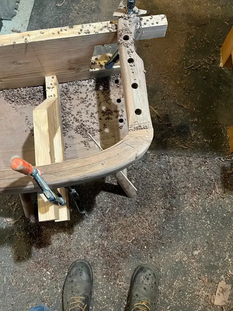
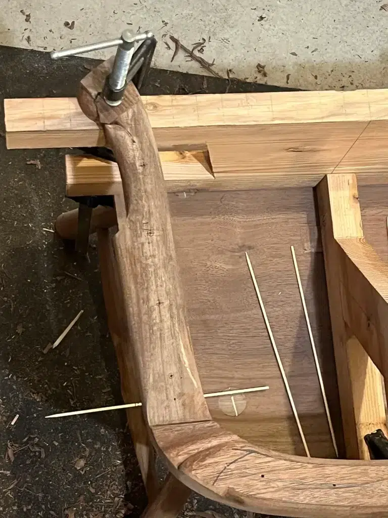
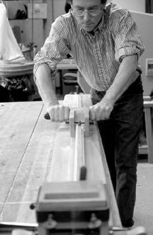
I have continued to explore the capabilities of this tool in the years since I first made it, and it has provided both mental and physical exercise. In action, I hold the tongue down with my finger as I push the strips through the machine for the return stroke, then I “draw strongly” on my handles. Depending on how deep the moulding is going to be, and this is dependent on the wave amplitude of the template, I will continue to make cutting strokes until the mouldings are complete. I take coarse cuts (Moxon would say “rank”) to start out with, but by the end, when the blade is bearing more-or-less continuously, the shaving needs to be thinner than paper. I can complete some moulding strips in 15 to 20 minutes, but deep mouldings in a hard wood take more time.
Any wood that is hard and relatively dense will work well for the moulding strips. Cherry is excellent, as are pear and maple. Many of the period mouldings are executed in either ebony or a fruitwood stained to look like ebony (ebonized). I have gotten by with poplar for moulding with a gentle wave. It’s best if the grain rises away from the pulling block so that the wood fibers are severed more obliquely. Earlier on, I mounted the moulding strips to the “racks” or guide bars with a few drywall screws shortened so that they did not come through the surface of my mouldings. I still had to make them relatively thick however, and they were only held firmly in a few places. Now I prefer to use the wood turner’s trick of gluing the stock piece to the template with pieces of heavy brown paper. The finished moulding is then taken off by splitting the paper interleaves, and scraping the glue and paper residue away.
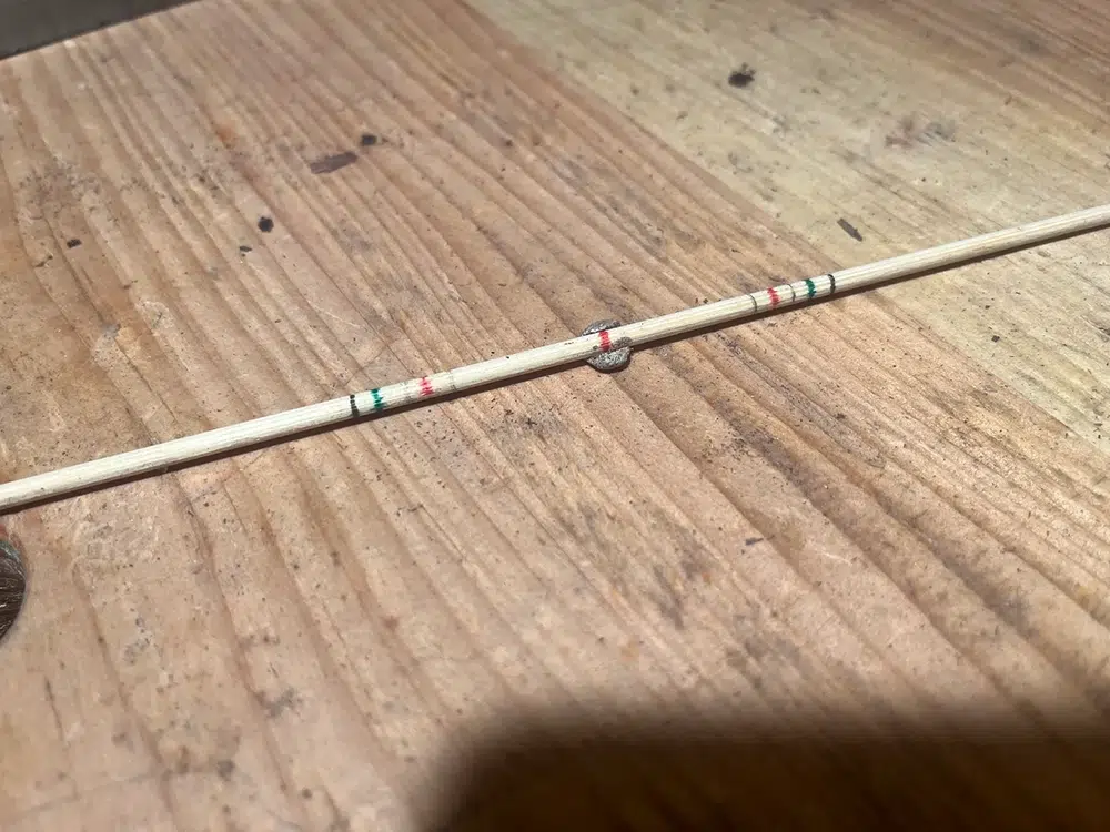
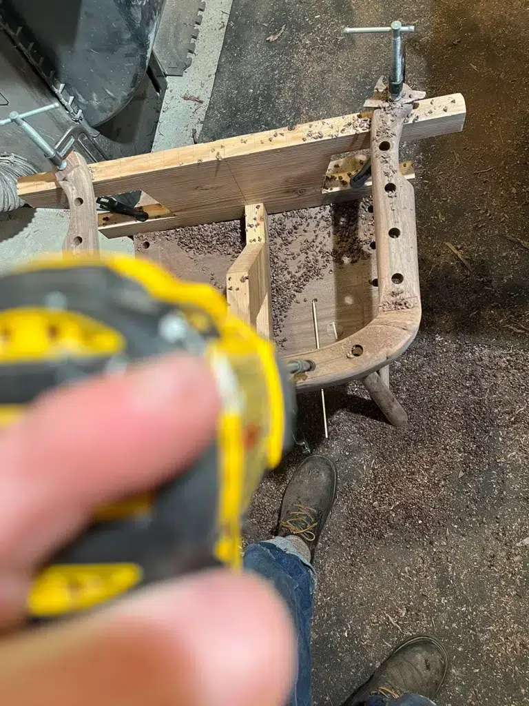
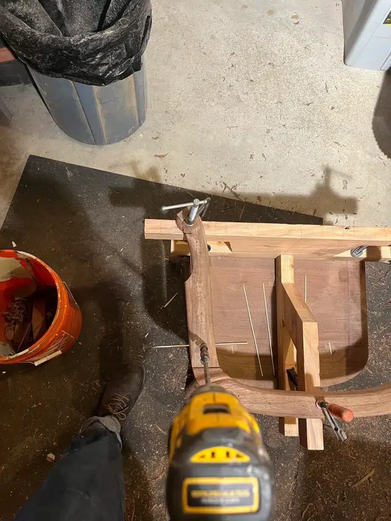
The “racks” are made of hard maple. I have hand-carved some of them after stepping off the intervals with a divider, by using the same gouge across the grain both bevel side up and bevel side down. I have also used a pin-indexing jig on my table saw and router table T-slide like those jigs used to cut box joints. I did this to create bars with tight waves that would have consumed a lot of time in carving. The mathematical accuracy of this method can be both an advantage and a disadvantage depending on your point of view. Historic ripple mouldings have subtle variation and character.
No sanding is required on a properly cut moulding. The blade leaves an almost polished surface in a wood like cherry. I also discovered that pushing the moulding back through the cutter-head for the return stroke burnishes the moulding against the polished bevel of the blade. Stain will greatly accentuate the wave appearance by selectively penetrating the severed wood fibers on the insides of the wave troughs.
1. Moxon, Joseph (reprinted from the 1703 edition). Mechanick Exercises or the Doctrine of Handy-Works. Scarsdale, NY, The Early American Industries Association (1979).
2. Robinson, T. “Handscraped Waves.” Fine Woodworking, 58 May/June (1986) 64.
19. Jutzi and Ringger, 46.