Yes, another brush. This one wasn’t on my list initially. When Mattias Hallin visited our shop this year, he brought some lovely small gifts. One of them was this incredible brush from REMOS.
The natural bristles are remarkably stiff and stout. Mattias explained that he uses this brush to clear his rasps of debris.
For years I’ve used a file card to clean my rasps. One side had stiff-ish natural bristles. The other side had stiff steel bristles. Mostly I used the side with the natural bristles. But it could never get all the sawdust out of the teeth. And eventually I would use (with a wince) the metal-bristled side to finish the cleaning job.
I don’t know if the metal bristles hurt the steel teeth of my rasps. But I didn’t want to find out.
The REMOS brush is incredible. It quickly cleans out the crevices under the rasp’s teeth without complaint. It is about 100-percent better than my old file card.
Thanks Mattias. This tool is a winner.
— Christopher Schwarz
To read previous entries in the gift guide, click here.
Our storefront – 837 Willard St. Covington, Ky. 41011 – will be open to the public from 10 a.m. to 5 p.m. this Saturday (Nov. 26). We will have our complete line of books and tools there for you to inspect, plus a somewhat-special giveaway for the first 144 customers.
(Uhhh, it’s a free jumbo eraser, branded with our logo. That’s the plan at least, if we don’t burn down the shop while branding these erasers.)
We’ll have some snacks and beverages. And if you ask to “see the clock” and are over 21 years of age, we will escort you to the machine room for a special treat.
Mostly it’s a chance for people to come and see the shop, check out our tools and workbenches and gab about woodworking. Lord knows what else we’ll have sitting around. There’s a Gibson chair on one of the benches. I’m making a staked dining table. And Megan has a weird orange rag on her bench you can ask questions about.
There are lots of great new places to eat while you are here. Right down the street we have The Empanada’s Box, which has great savory and sweet empanadas. Try Olla, a new Mexican place a couple blocks away – great birria tacos. Plus The Standard, Mama’s on Main and Cedar. You will not go hungry in Covington.
One of the many fantastic tips I learned from “The Belligerent Finisher” was using common household materials to burnish wooden surfaces. Burnishing compacts the wood and can add a gorgeous texture.
Author John Porritt has several simple tools he uses for this. The coolest one is a chainmail pot scrubber, which is great fun to use. You can find these at any good household/kitchen store. I experimented with several different kinds. Some had bigger rings. Some had very fine rings. I preferred the smallest rings. The fine one I like looks like the one shown here. I bought mine at a local restaurant supply store. Look around, and I’m sure you’ll find one.
I’ve been using the pot scrubber on my chairs before applying soft wax. I use it mostly on protruding tenons and on the chair’s hands. The burnishing rounds over any hard edges, making them kind to the user’s hands.
The pot scrubber is quite similar to using a polissoir, except that it excels at working on curved and shaped surfaces. The polissoir, on the other hand, is great for large flat surfaces and is tricky to use on edges.
As always, the world of finishing is endlessly surprising.
— Christopher Schwarz
To read previous entries in the gift guide, click here.
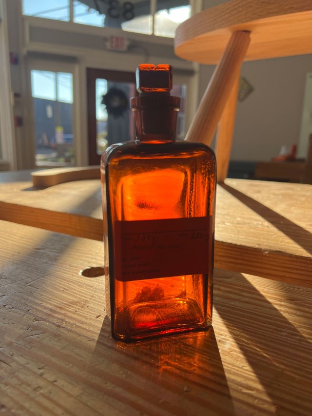
This entry is the sister to yesterday’s entry on our fancy plant mister. We found these vintage glass apothecary bottles and immediately bought some for shop liquids. We keep our backup supply of 50/50 water/alcohol potion in it.
The bottles are 7” tall and hold 250ml. The best part is that the bottle’s opening and its stopper are ground glass. So opening and closing the lid is a sensory pleasure (look, I know I’m weird).
The bottles are a dark brown glass. Ours came with an old pharmacy label on it that was covered in handwriting. Our bottle held Akutol, a first aid spray.
These bottles are gorgeous things that you don’t see much anymore.
OK, enough whimsy.
— Christopher Schwarz
To read previous entries in the gift guide, click here.
As a woodworker, sometimes I ask too much of the wood.
Instead of just putting a cushion on a chair, I’ll do everything possible to force the wood to be as comfortable as possible. Naked. With no help from anything cloth, leather, foam, feathery or furry. So, I have spent years (almost two decades) learning to saddle seats – plus dial in the angles of the back and arms and seat deck – to increase the chair’s bare comfort.
But while looking at hundreds of historical chairs, I’ve seen hints of a reality that I should acknowledge more often. When it comes to comfort and warmth, wooden chairs are often assisted by wool, animal skins and cotton (to name a few).
For several years I’ve encouraged readers and customers to use sheepskins on their wooden chairs, which add lots of warmth and comfort (my favorite source for these is Driftless Tannery).
A Welsh interior at St Fagans National Museum of History.
If sheepskins add too much bulk or warmth, try a wool blanket. While I was visiting St Fagans National Museum of History, I was struck by how much of the seating there was displayed as covered in woolen blankets or quilts.
While some might be put off by covering your work with a blanket, I think they are a nice complement to the woodwork – two colorful, renewable, durable and handmade objects working together to add ease and beauty to our lives.
A Forest chair in Shelburne, Vermont.
This relationship between blankets and chairs is old. Recently Angela Robins, sent me a photo of a Forest Chair in Shelburne, Vermont, that had been modified to wrap the sitter in blankets and warmth. I love its almost skeletal appearance – and it looks naked without its coverings.
Sometimes the union between blankets and chairs is somewhat hidden.
One of the small nails on the underside of a chair’s armbow.
Antiques dealer Tim Bowen in Wales recently pointed out some small nails on the underside of the arm of a stick chair. The nails’ heads protruded slightly, perhaps about 1/8”. And they weren’t structural or part of a repair.
Tim said he sees often finds these nails on old chairs and they are covered in strands of wool or other cloth. He suggested the nails acted as hooks to help keep blankets in place on the chair.
So during my most recent trip to Wales I brought back a lovely Welsh wool blanket. And I have a box of tiny old headed nails – more like escutcheon pins, really – with square heads. Just like the nails that Tim showed me.
It’s time to introduce my chairs to a new friend from the sheep world.