Kale and I had a brief discussion of mouldings and moulding planes last week as she worked on her tool chest, and raised a square panel for one piece using a rabbet plane. And that reminded me of Peter Nicholson’s discussion of moulding profiles, which I love in large part because of the mellifluous nomenclature. Scotia. Quirk. Cavetto. Astragal. Yum. Here is part of that text, which teaches you how to draw a handful of profiles, excerpted from our reprint of “Mechanic’s Companion.”
§ 68. To draw the several kinds of Mouldings made by Joiners.
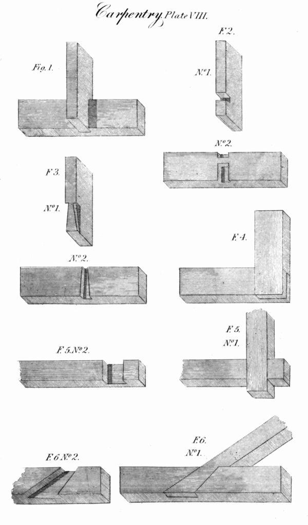
An astragal is a moulding of a semi-circular profile; its construction is so simple that it would be unnecessary to say anything concerning it. Fig. 1. [Editor’s note: Ha.]
There are two kinds of beads, one is called a cocked bead, when it projects beyond the surface to which it is attached, see Fig. 2; and the other is called a sunk bead, when the sinking is depressed beneath the surface of the material to which it is attached, that is, when the most prominent part of the bead is in the same surface with that of the material, Fig. 3.
A torus in architecture is a moulding of the same profile as a bead; the only difference is, when the two are combined in the same piece of work, the torus is of greater magnitude, as Fig. 4; in Joinery the torus is always accompanied with a fillet. Fig. 5. single torus moulding.
The Roman ovolo or quarter round, as called by joiners, is the quadrant of a circle, Fig. 6. When the projection and height are unequal, as in Fig. 7, take the height B C, and from the point B describe an arc at C, and with the same radius from A, describe another arc cutting the former at D, with the distance A D or D B describe the profile A B. This is generally accompanied with fillets above and below, as in Fig. 7.
The cavetto is a concave moulding, the regular profile of which is the quadrant of a circle, Fig. 8; its description is the same as the ovolo.
A scotia is a concave moulding receding at the top, and projecting at the bottom, which in this respect is contrary both to the ovolo and cavetto; it is also to be observed, that its profile consists of two quadrants of circles of different radii, or it may be considered as a semi-ellipse taken upon two conjugate diameters, Fig. 9.
To describe the scotia, divide the height A B into three equal parts, at the point 2 draw the line 2 C D, being one-third from the top, draw E C perpendicular to C D, with the centre C and distance C E describe the quadrant E F; take the height A 2 and make F D equal to it: draw D G perpendicular to F D, from D with the distance D F describe the arc F G, and E F G will be the profile of the scotia. This moulding is peculiarly applied to the bases of columns, and makes a distinguishing line of shadow between the torii.
The ogee is a moulding of contrary curvature, and is of two kinds: when the profile of the projecting part is concave, and consequently the receding part convex, the ogee is called a cima-recta, Figs. 10 and 11 ; and when the contrary, it is then called a cima-reversa, Fig. 12.
To describe the cima-recta when the projection of the moulding is equal to its height, and when required to be of a thick curvature, Fig. 10. Join the projections of the fillets A and B by the straight line A B; bisect A B at C, draw E C D parallel to the fillet F A, draw A D and B E perpendicular to F B; from the point E describe the quadrant B C, and from the point D describe the quadrant A C, then B C A is the profile.
To describe the cima-recta when the height and projection are unequal, and when it is required to be of a flat curvature, Fig. 11. Join A B and bisect it in C, with the distance B C or C A from the point A describe the arc C D, from C with the same radius describe the arc A D cutting the former in D, the foot of the compass still remaining in C describe the arc B E, from B with the same radius describe the arc C E, from the point D describe the arc A C, from the point E describe the arc C B, then will A C B be the profile required.
The cima-reversa, Fig. 12, is described in the same manner.
Quirk mouldings sometimes occasion confusion as to their figure particularly when removed from the eye, so as frequently to make one moulding appear as two.