This is an excerpt from “Cut & Dried” by Richard Jones.
The word grain brings to mind several characteristics of wood. It is an indistinct word requiring context. If someone says, “That wood is beautiful,” what do they mean? They might be referring to the patterns, colours, striking illusory figuring or the lustre. Alternatively, the comment may be in response to touching the polished wood, and it is a reaction to its smoothness or roughness.
I think every person, whether they be a woodworker or lay person, has an instinctive concept in almost any circumstance of what they think the nebulous word “grain” means. In truth, it is really necessary for the sake of accuracy and the ability to communicate effectively to provide some context when discussing the subject. Perhaps most commonly inferred or understood amongst woodworkers when we say grain is a reference to its orientation within the longitudinal axis of the trunk or limb, e.g., long grain, with the grain, across the grain or cross-grain. This really summarises the primary characteristic of grain – its direction. The word grain holds fuzzier meanings for laypeople. They recognise the wood displays patterns and shapes visible on the surface along with concepts such as lustre and colour. They generally have an indistinct concept of such characteristics as strength as it relates to grain direction or the importance of allowing for expansion and contraction.

A parallel exists when I deal with inexperienced woodworkers. Their inexperience sometimes leads them to make elementary construction errors. They sometimes inadvertently make two sides and a top of a solid-wood box where the long grain runs conventionally up and down the sides and left to right on the top. Then they add a bottom where the long grain runs front to back. In the same vein, new woodworkers will mistakenly fix a solid-wood table or cabinet top down to a framework. Both these examples of construction errors are likely to lead to failure because neither allows the wood to expand and contract across the grain.
Grain
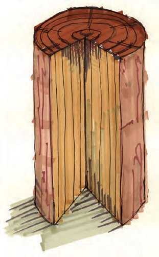
Terms used to describe grain putting the subject into context are “end grain,” which is a transverse crosscut surface, e.g., the view of the end of a board; “side grain,” which is a tangential cut parallel with the growth rings, and “flat grain,” a plank cut out of a log at right angles to the growth ring, i.e., radially cut.
Further definitions adding specificity to grain descriptions in the log or trunk of a tree are as follows:

Straight grain. The fibres run parallel to the long axis of the tree. An example of a correctly sawn tangentially cut board shows centred-arching grain patterns in which the legs of the arches are of roughly equal length as is their angle from the centre line of the board (figures 13.1, 13.2 and figure 13.3).

Oblique grain, cross grain or diagonal grain. The fibres show as anything from a slight deviation to a severe deviation from straight grain. The least deviation is usually described as oblique grain; the most severe, diagonal grain. However, many sawmill operators, wood sellers and woodworkers themselves make no distinction between the names and describe all deviations as cross-grain, oblique grain or diagonal grain depending on their preferred nomenclature and local custom. In a cut board, this may be caused by tangentially sawing a spiral-grain log, or through a poor choice of cut made by the sawmill operator. Boards cut from crooked logs and logs with significant sweep frequently show cross-grain defects. Another cause of cross-grain is because of the sawmill operators choice of cut when milling heavily tapered logs, i.e., a log that has a small diameter at one end and a much larger diameter at the other. Cutting parallel to the pith results in cross-grain boards, many of which are tapered in their width. To win straight-grained boards the solution is to “taper cut,” wherein the log is cut parallel with the bark. This too results in some planks tapered in their width, particularly as the cuts approach the pith. However, this form of cutting does result in more clear, straight-grained boards because the greatest majority of the knots in a log are clustered around the pith, the tree’s original stem. A mature tree in a forest with a trunk of sizeable girth puts out relatively few side branches compared to a young sapling.
— Meghan B.


