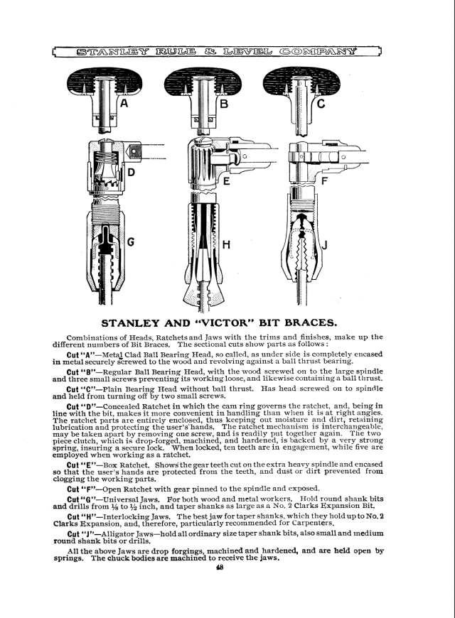
One of the best ways to understand hand tools is through the eyes of people who used them to make a living 100 years ago. Our reprint of the 1914 “Stanley Tool Catalogue No. 34” shows nearly every tool needed in a hand-tool shop, from the chisels to the butt gauges to every sort of plane in the company’s line at the time. The text explains what each one was used for and how it functioned differently from other similar tools. The catalog also had fantastic exploded views of many of the complex tools, such as the company’s miter boxes and braces, as shown in the excerpts below.
To mark the five-year anniversary of Crucible Tool, we collaborated with artist Jennifer Bower to hand engrave one side of 10 Crucible Lump Hammers with our logo surrounded by decorative foliage.
These 10 special tools are now available, and are $350 – which basically covers the costs of making these special tools and no more – plus actual shipping charges. They are available only in the U.S.
So that everyone who is interested has an equal chance of getting one, we’re asking those who want one to send an email to lapdrawing@lostartpress.com with the subject line: hammer (please do not send other email to that address; it won’t get read until our next drawing). In the email body, please include your name, phone number and mailing address. All emails must be submitted by 5 p.m. (Eastern) on Wednesday, Feb. 2. That evening, or possibly the next day, we’ll randomly select the winners from among the entrants. The winners will receive an invoice they can pay online.
And if we don’t have 10 interested parties, well, I’ll get a gorgeous new hammer (one that I won’t use to knock out old plaster)!
A few months back, Daniel Ackermann, Chief Curator and Director of Collections, Research and Archeology at the Museum of Early Southern Decorative Arts, sent a note inviting me to give a presentation at the museum’s March 17-19 conference. As someone who was diagnosed with an incurable condition typically associated with a short prognosis, I replied first with that disclosure, expecting the organizers to change their minds. But the people at MESDA are a hardy lot. They already knew about my condition and said that dealing with the pandemic throughout 2021 had shown them how to roll with the punches. Should it prove impossible for me to attend, Daniel said they’d devise a back-up plan.
I was honored to be asked. Although I haven’t visited the museum, I’d heard of it from distinguished furniture making friends Mike Mascelli, Steve Latta and Bob Van Dyke. A plain Southern cousin to northeastern counterparts such as Winterthur, MESDA had always struck me, personally, as a kindred spirit – a scrappily defiant, sometimes-overlooked storehouse of history and culture no less worthy of appreciation and study. What better way to keep the lessons of history alive to guide our own times than by offering visitors and scholars insights into a region’s material culture, which inevitably reflects its dominant (and less-dominant) social and economic forces? The theme of the conference was especially appealing: “From Forest to Furniture: New Approaches to Materials & Making.”
Pick one or more objects from our collections and use that as your focal point, Daniel suggested. So I pored through the online catalog of paintings, textiles, ceramics, architecture, furniture and more. A few pieces sparked my interest, though connecting to them in any presentation I would want to give felt a little forced. Then, at the bottom of the screen, a gorgeous object leapt into view: a tawny painted blanket chest adorned with dark spots, supported by a decoratively scalloped skirt – it brought to mind a leopard padding through the grass. It was “probably made for Nancy Wyatt Adams who lived in the foothills of Wilkes County before the Civil War.”
The catalog describes it this way:
“Chest joined at the four corners with rather chunky dovetails; base molding, scalloped skirt, and feet made from one piece of wood, three pieces forming the base are mitered at the front corners and nailed on; lid molding is nailed onto front, but each sidepiece was through-tenoned first and then nailed on; sturdy hand wrought pintle hinges holding the lid onto the case; nails used throughout the chest appear to be cut; no till on the interior; first painted with a red/orange base coat and then covered with black dots placed in a somewhat orderly pattern of straight lines.
STYLE: Both the basic construction and unsophisticated decoration of this chest strongly suggest it was a completely homemade product, and not one of an established cabinetmaking shop. As with many “neat pieces,” that is part of its charm.”
Chunky dovetails? Lid moulding nailed on? This “completely homemade product” was my piece. There are plenty of others who enjoy writing about and being associated with All Things Fine. Give me the stuff that someone made with love to serve a daily purpose, rather than as a badge of “success” or “good taste.”
Even more compelling for me than its homespun origins and catlike character is that the Adams’ youngest daughter, Elizabeth, remembered her family packing the chest with treasured possessions and concealing it in a bed of leaves in the forest for safekeeping during the Civil War. Fortunately the chest and its contents survived, presumably undiscovered, and were handed down through the generations before Henry and Nancy’s great-great-granddaughters, Winnie Luffman, Jean Luffman Humber and Lucy Luffman Dearing, donated it to the museum in honor of their mother, Butrice Johnson Luffman.
The piece resonates with me on multiple levels and I’m delighted at the prospect of working with it for a talk about materials and making.
The following is excerpted from “The Workshop Book,” by Scott Landis. First published in 1991, it remains the most complete book about every woodworker’s favorite place: the workshop.This edition was published in 2021 with a new foreword by Roy Underhill.
“The Workshop Book” is a richly illustrated guided tour of some of the world’s most inspiring workshops — from garage to basement shops, from mobile to purpose-built shops.
Landis traveled all over North America to discover the workshops featured in this book. The result is an intriguing and illuminating look at multiple successful approaches to shop layout.
Clamps, like other hand tools, live on the wall in many workshops. Hanging his clamps was one of the first projects Bob Allen undertook when he set up his new workshop in Raleigh, North Carolina. Allen’s open layout makes it easy to find the right clamp in a hurry, but to speed the process, he also marked each clamp with its maximum clamping distance.
Ken Bishop’s rolling clamp caddy. (Photo by Ken Bishop.)
Allen’s layout is attractive if you have the space, but clamps may be needed anywhere in the shop, wherever the action is. For that reason, a lot of woodworkers store their clamps on rolling carts. Many clamp carts hold one or two types of clamps well, but Ken Bishop’s rolling clamp caddy seems as comfortable with long pipe and bar clamps as with wooden handscrews and small C-clamps. Bishop’s caddy is built from standard 2×4 lumber, mounted on a plywood base and 2-in. casters. All the horizontal components, which carry the clamps, are 24 in. long. The plastic bucket contains an assortment of hardwood glue blocks.
Rotary clamp rack. Note: Conduit may be suspended from a 6-in. wide plywood crosspiece between ceiling joists, as shown, or though-bolted directly to the joist.
Robert Markee, of Iowa City, designed the rotary clamp rack shown in the drawing [above] to hang from the joists of his workshop ceiling. “It’s nothing but a lazy Susan, hung from the top,” he explains. Markee has four of them in his shop, two filled with clamps (93 on each one, at last count) and the others draped with hammers, screwdrivers, wrenches and various other hand tools. The rack is suspended by bolts through the top and bottom of the central conduit, and is held in place by the weight of the tools. “Heavens,” Markee says, “I think I’ve got 50 lb. on there!”
Lewis Judy’s clamp can.
Clamp racks don’t get much simpler than Lewis Judy’s galvanized clamp can. Judy bored concentric rings of 1-in. dia. holes in a plywood disc and jammed it inside the top of a garbage can to receive bar clamps. He spaced the holes about 3 in. apart, staggering them as they radiate out from the center. The bottom of the can is filled with sawdust to protect it from the long bars. “I don’t know how many it holds,” Judy says, “but I can’t lift it.”
Alex Dolese with her dog, Watson, “a mutt” who’s part border collie.
Every so often it’s good to remind yourself that despite all the stuff that’s going, well, let’s say less swimmingly than we would prefer, plenty of other things are getting better.
When I started woodworking in 1980, there were few other women to be found among furniture makers in rural English shops. I certainly didn’t know any, though I’d heard that some were out there. The first professional woman woodworker I recall meeting was Faye at the Wall-Goldfinger shop in Northfield, Vermont, where I signed on in 1987 after returning to the States. Soon after, the company added another woman, who had worked as a patternmaker for Vermont Castings. In the late ’80s, three women in a shop floor crew of eight or 10 was a big deal. That proportion of women to men would still qualify as unusual today. (And Faye, if you’re reading this, I hope the “e” on your name is correct.)
Fast forward to the late 1990s on a jobsite in Bloomington, Ind., where a carpenter mentioned he was thinking about opening his own business. He was going to call it Venus Woodworking in the hope that potential customers would infer from “Venus,” a family name, that the business was run by a woman. That was the first time it had ever occurred to me that being a woman in this field might give one an edge, at least in the eyes of some potential customers. At that point I had spent years hiding behind the gender-opaque business name “NR Hiller Design,” concerned that people might assume the quality of my work was low because I wasn’t a man. If you think this sounds paranoid or bizarre, I’m here to tell you that I’d had plenty of experience by then to convince me that such notions were widespread, at least in our south-central Indiana locale. I hoped that this opacity might at least give me a chance to make a good impression by phone, which was how most prospective customers made preliminary contact in those days.
Alex outside her Bozeman, Mont., shop with her business logo on the door.
This preamble should go some way toward explaining why I found it rewarding to hear Alex Dolese explain that while, in daily life, she prefers to go by “Alex,” she named her business Alexis Dolese Woodworks precisely to leave no doubt that she’s a woman. In the past several years it has become downright cool to be a woman in woodworking, and women are doing some of the most dazzling work to be found today.
Alex was born in Missoula, Mont., in 1995. Her parents, Tom and Jennifer Dolese, are partners in their business, Terra Firma Design, now located in Bellingham, Wash. Tom designs and builds furniture; for select pieces, Jennifer creates marquetry and stained glass that complements it.
As a child, Alex spent lots of time in the shop. “My first memory is going to the workshop in Missoula…and pounding nails,” she says. “My dad would give me a scrap piece [of wood] and I would pound nails into it.” Other childhood memories of her parents’ workplace: “There were lots of parties at the woodshop. And I remember there being Wonder bread, which I wasn’t allowed at home. It was a real treat going there!”
Start ’em young. Alex practicing with the horizontal mortiser her father, Tom Dolese, created.
In 2004, when Alex was 9, she and Tom built a cherry picture frame that she still has in her home. Although it was her first time building something with him, they made the frame with pegged mortise-and-tenon joints, adding faux through-tenons for decoration.
In middle school, Alex had a pen-turning business. She sold her pens at the farmers’ market and at a yearly show in which her dad took part. That business, she adds, “was heavily subsidized by my dad. We learned to turn together, which was really fun. My dad was never, like, ‘you should come and sand or build something.’ He wanted me to make that move. I was interested but never felt pressure to do it.”
Turning pens.
Her interest in woodworking dwindled in high school. A competitive track athlete, Alex applied to college at Montana State University in Bozeman, which has a track program in Division I. She started studies in ceramics; many of her parents’ friends made their living as artists, so a career in creative work seemed within reach. But on a break a year and a half in, she discovered her perspective on woodworking had changed for the better; she remembers thinking “I love this medium so much more.”
Alex with her first chair.
At that time, she says, “I was living in this house and I would [pass] a house getting framed. They had a few women on their crew. I thought ‘That looks like so much fun!’ I called my dad and told him I wanted to build a tiny house; my parents had built quite a few homes while I was growing up, so I had seen the process.” She had an inheritance from her grandmother and thought about starting a business as a general contractor. Her dad asked “all the business questions” and encouraged her to start by building a house of her own. “I went down that path pretty quickly and thought, if I’m going to learn this, why don’t I learn what my dad’s doing in the shop?” Having access to her dad for instruction and guidance would be invaluable.
So she went ahead and built her own house. At 20, Alex began the design work, collaborating with Jennifer. A retired architect named Bob was taking a few classes from Tom and overheard some of their conversations. “’OK,’” he said. “’Where’s the sun coming from? Let me do some drawings for you. Let’s think about the mountains and the sun so you’ll be getting passive solar.’”
After hiring a draftsperson to whip the drawings into a form acceptable to the authorities, Alex applied for building permits from the city. In the meantime, she went to work for her dad, spending seven days a week in the shop. I absolutely love being here and doing this, she realized. She made a dining room chair, then a chair with an adjustable back. She took a dining chair class. There were lots of other jobs, from picture frames to beds – “just a lot of stuff to help my dad.”
She hired a builder, and they broke ground on her house in the summer when she was 21. Alex worked side by side with the crew, through the framing all the way to drywall. “We got a hard bid from [the builder] and then experienced him adding a bunch of costs to the bid without any change orders.” So she fired him at the drywall stage. (This should explain why she prefers not to share his name.) Then she went back to Bellingham, where her parents had moved when she was about 9, to build her cabinets and trim with her dad over winter.
In the attic. Alex worked side by side with the crew to build her house.
Jennifer (a.k.a. “Mom”) laying floorboards.
Alex wired her garage as a shop but found that her tools didn’t fit well in the space. Instead, she rented shop space in Bozeman. The 3,000-square-foot building was originally split into three sections, of which she had some 700 square feet; with part of that space split between a spray booth and bathroom, she decided it wasn’t big enough, so she moved to her current shop, a 1,500-square-foot space with radiant heating in the floor.
Home.
Clientele
Alex launched her business early in 2020, just when Covid hit. “It was kind of a blessing,” she reflects, “because I needed that time. I have a rental property in my house, so I was able to not have to make money right away. I needed that time away from my dad and my mentors to figure out Am I doing this right? and make mistakes without having someone there to correct them.” It’s easy to feel you can do anything when you’re in someone else’s shop who can set up machines for you and share advice about how to fix a split or help move a heavy carcase, but some of the most important learning happens when you find yourself having to solve problems on your own.
Bozeman is booming, so prospective customers began to find Alex quickly through word of mouth. “Being a young woman has helped,” she acknowledges. “People are excited to hire me because I’m young and female and it’s kind of a helpful marketing tool. There’s this [wide-ranging] conversation [about supporting] minorities and encouraging people. A lot of more progressive people are moving to Bozeman who are interested in furniture. I’m also communicative; I like working one on one with clients. One of my favorite things is co-designing with clients. That’s an experience a lot of older woodworkers aren’t really interested in.”
Alex with students in the first chairmaking class she taught.
Alex and her father, Tom , during a class he taught at the Port Townsend School of Woodworking for which she assisted.
She teaches, too, and has a number of younger women interested in building furniture with her. She has worked as a teaching assistant for her dad in classes at the Port Townsend Woodworking School, where she has also taken classes. A couple of years ago, when the school asked Tom to teach another class, he told them he was retiring and suggested Alex teach it. They agreed. “They’re really encouraging and give people chances,” she says. In 2021 she taught a 10-person class. This year she’s scheduled to teach a women-only class. “The community that school brings in is really exciting,” she thinks. Her friend Annalise Rubida has worked as her teaching assistant.
Annalise Rubida and Alex showing off matching hats made by a student.
Though Tom plans to retire, he hasn’t quite managed to pull himself away from the shop. He recently took on a couple of apprentices and continues to share his encouragement and expertise. His current shop is close to downtown Bellingham – “where all the breweries are,” Alex adds, right in the heart of town.
“I feel like I’m so new in this career,” she says. “I’ve only been in business two years, and I feel so lucky to be doing what I’m doing. There [are] endless possibilities in what I could do. I really enjoy teaching and have been blessed with wonderful mentors in woodworking. I’m excited to share. It’s this wonderful wealth of knowledge we get to tap into. I want to encourage that and hopefully grow more of a community. Instagram has been a tool to connect with woodworkers and get to know people. It’s really exciting.”
She’s looking forward to developing her own style and building her own line. “I just feel like I can make anything I want, which is really cool.”
Tom and Alex with kitchen cabinets they built together for her house in Bozeman.
For me, after fighting low expectations, ridicule and near-endless self doubt over much of my career as a builder of furniture and cabinetry, Alex’s freedom from gender-based obstacles is evidence that good things are happening all around us; in a culture that floods our waking consciousness with news of suffering and evidence of widespread despair, we have only to give these happy developments our attention.
(And in case you’re wondering how someone can get so much done, Alex will gladly acknowledge that her house remains “a work in progress.”)