This small hammer (the head is about 4 ounces) is ideal for setting and sinking small nails. The cross-peen (sometimes called the cross-pane) starts the nail. You hold the nail between your thumb and forefinger and strike it with the peen. (The peen misses your fingers and hits the nails.) Then you turn the hammer around and finish the job with the hammer’s round face. The cross-peen is also ideal when setting moulding planes. And the Warrington is an excellent plane-setting hammer. Its weight and size are perfect for making lateral adjustments to block planes or bench planes.
The following is excerpted from Christian Becksvoort’s “With the Grain: A Craftsman’s Guide to Understanding Wood.” The three woods I chose (from the 30 he covers) are my favorites from which to build tool chests, because they are lightweight and relatively inexpensive (and because they have a good “mash factor,” and thus can make you feel like a demi-god dovetailer – if your joints are technically a smidge too tight, they can be squeezed together, no splits, and look perfect).
“With the Grain” is the book about wood that we wished we’d had when we started woodworking. It is, above all, succinct, easy to understand and perfectly suited for the furniture-maker. As important as what is in its 160 pages is what is not. It’s not a detailed analysis of cell growth. It is not a heap of tables and equations for figuring truss loads in residential construction. It is decidedly not a scientist’s approach to the material. Instead, “With the Grain” contains the facts you need to know at the lumberyard, in the woodlot and in the shop. It gives you enough science so you understand how trees grow. It explains the handful of formulas you have to know as a furniture-maker. And it gives you a hearty dose of specific information about North American species that will inspire you.
– Fitz
Woodworkers should have a rudimentary knowledge of their material. Understanding wood and its characteristics, how it grows, how it reacts and how it is best used, leads to a deeper appreciation of the wood itself.
This book is limited to the trees of North America. The selection of timbers on this continent is vast and varied. It takes years to become really familiar with all the working properties of even a few species. The range of textures and smells, colors and grain patterns is enough to satisfy any purpose. The secret lies in using the right wood for the right reason. Each wood should be explored, used, tested and evaluated. Local woods are relatively cheap, readily available and can be used for a variety of designs. In my opinion, it is far better to use material at hand, and use it well, rather than to import exotic woods with no knowledge of their working properties.
Except for the leaves of poison sumac (Rhus vernix), which cause dermatitis, and perhaps the dust of redwood (Sequoia sempervirens) and red cedar (Juniperus virginiana), which can cause allergic reaction in some people, North American woods are generally considered safe (although dust masks should be worn when exposed to any wood dust). Of the 30 woods listed in this chapter, only a handful are well known to most furniture makers. They are the popular commercial woods and are available at most well-stocked lumberyards and wood wholesalers. The remaining species are not often commercially available. Some don’t grow in sufficient quantities and others don’t grow to sufficient size to be harvested for the mass market. Yet these are marvelous timbers, beautifully colored, with a wide range of uses and working qualities. They, and others like them, are underutilized. What could be more appealing than a custom-made side table, wall cabinet or bench made of sassafras, sycamore or persimmon? If the tree was cut locally, or even on one’s own land, the wood will be all the more special. These underutilized woods should be tried and used. Often they are available for a fraction of the cost of the more popular species.
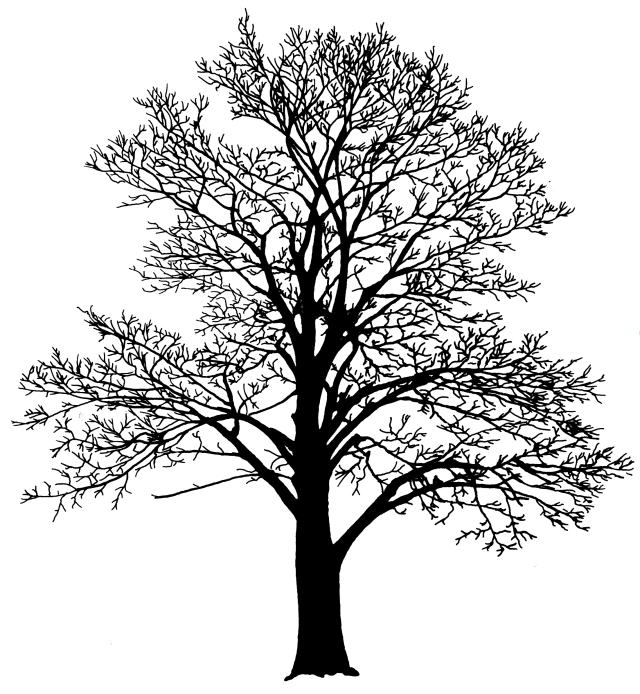
This section is intended as a reference, a guide to the more common trees that can be easily identified by their shapes, twigs, leaves and bark. For some trees, such as red and white oaks, a more comprehensive manual is recommended to delineate the individual species.
The silhouettes illustrated indicate each tree as an open-grown specimen, field-grown under uncrowded conditions. This basic shape is genetically programmed in the seed. The same tree grown under forest conditions may be quite different; it may have 40′ (12 m) of clear trunk and few spindly branches competing for sunlight in the forest canopy. The forest-grown shape is environmentally induced by shade and the competition from surrounding trees. By using the other characteristics, both shapes should be recognizable as the same species.
The trees are listed by families, in the generally recognized progression from simple to more complex plant structure.
Eastern white pine is also referred to as Northern, soft, balsam or Weymouth pine. The name Pinus refers to the pine family, while strobus means cone. The tree’s natural range is from Newfoundland to Manitoba, south to Wisconsin and Iowa, and east to the Appalachians down to Georgia. Ordinarily it reaches heights of 80′-100′ (24-30 m). Old king’s broad arrow pines, used for masts in the royal navy, sometimes grew to more than 200′ (60 m). White pines can reach 400 years of age.
Pines, like most conifers, grow a straight central trunk. The branches of white pine grow almost horizontally, usually in groups of five. The pine shoot borer, an increasing pest in pine-growing areas, kills the leader, forces one of the branches to take over as leader and results in deformed or multiple trunks. Pine needles are 2″-5″ (5-12.5 cm) long, grow in bundles of five, and are surrounded by a papery sheath at the base which drops off after the first season. White pine cones are 4″-8″ (10-20 cm) long, fairly thin, quite flexible and take two years to mature. The bark forms gray scaly ridges.
End grain cross section (25x) Courtesy of Univ. of ME School of Forest Resources, A. Autio
Face grain, plain sawn
Sapwood of white pine is pale yellow-white. Heartwood is cream to light reddish-brown when freshly sawn, turning to a warm reddish-brown on exposure to air and light. Old, clear heartwood is often referred to as pumpkin pine. The wood contains a fair amount of pitch. It is generally straight, even grained and light, with a density of 25 lb/ft3 (.39 g/cc) at 12 percent MC. It is a real workhorse in most shops, used for jigs, braces and mock-ups. As a pattern wood it has no equal. Quartersawn white pine is the most well behaved of all the native woods. Pine’s ease of sanding, chiseling and planing makes it an ideal secondary wood. When used as such, it fills the entire interior of a chest or cabinet with a clean, woody odor. It is also used as a primary wood. Most of New England’s painted antiques are constructed of white pine. Shellac over the knots prevents the pitch from bleeding through. Perhaps it appears at its best when left raw, or oiled to age naturally.
Sugar pine is also known as purple cone pine, or big pine. The Latin name refers to Dr. Aylmer Lambert, a British botanist. Because of its size, it is one of the most prolific producers of timber. The tallest of the pines, it commonly reaches heights of 160′-180′ (48-54 m) and diameters of 4′-7′ (1.2-2.1 m), and lives 300 to 500 years. Its natural range is from Oregon through California. Sugar pines prefer loose, well-drained sandy loams, and grow best in areas having over 40 inches (100 cm) of annual precipitation. Like the Eastern white pine, sugar pine has five needles per bundle. They are 2-122 – 4 inches (6.3-10 cm) long, bluish-green in color, and remain on the tree for three years. The cones are purplish and erect when immature, shifting to a hanging position as they ripen the second year. They are 12″-20″ (30-50 cm) long, the largest of all pine cones. Sugar pine bark is deeply and irregularly grooved, with scaly, cinnamon-brown ridges.
Bark Courtesy of U.S. Forest Service
End grain cross section (25x) Courtesy of Univ. of ME School of Forest Resources, A. Autio
Face grain, quartersawn
The sapwood is pale, while the heartwood is light beige-yellow, with prominent brown streaks. These are resin canals, filled with crystallized resin. Sugar pine has a distinct sweet odor when cut or sawn. The aged wood does not darken like white pine, but turns light brown. With a density of 25 lb/ft3 (.39 g/cc) at 12 percent MC, the two woods are very similar in working qualities, although sugar pine is slightly coarser. It is used extensively in general millwork for sash, doors and all types of trim and mouldings, as well as foundry patterns, building construction, signs, plywood, crates and even organ pipes. It is not decay-resistant, and should not be used outdoors. The wide, clear widths available make it an ideal cabinet wood.
Basswood is also known as whitewood, lime, bee tree or more commonly, American linden, which is a literal translation of its Latin name. It is a tall, 60′-110′ (18-30 m) stately tree, frequently used as an ornamental, and it is well-adapted to city conditions. The species grows best in moist, fertile soil, where it grows rapidly, but only reaches 100-140 years of age. It usually grows with other hardwoods, rarely in pure stands. The natural range is from New Brunswick through southern Canada into Manitoba and South Dakota, south to Kansas and Arkansas and east to North Carolina and Virginia.
Bark
Basswood leaves are asymmetrical, heart-shaped, about 4″ (10 cm) long and 3″ (7.5 cm) wide. The tree is highly prized by beekeepers for its fragrant, creamy white flowers. These hang in clusters attached by a single stalk to a leafy bract. Fruits form as small woody spheres. The bark is dark gray and in older trees is furrowed with flat, scaly ridges.
End grain cross section (25x) Courtesy of Univ. of ME School of Forest Resources, A. Autio
Face grain, plain sawn
Basswood is very light in color, with almost white sapwood and creamy white to pale brown heartwood. Its weight is also light, having a density of 26 lb/ft3 or .41 g/cc at 12 percent MC. This relative softness makes it easy to indent with a fingernail. It has a very faint odor when freshly cut, no taste, straight grain and virtually no figure. The pores are diffuse and the growth rings are indistinct, with almost no difference in the hardness of early- and late-wood. This softness and even texture makes it an ideal wood for carvers. These characteristics also make it a sought-after wood for tubs, excelsior, slack cooperage, boxes, apiary supplies, venetian blind slats, and assorted wooden ware. Basswood warps and checks very little after drying and is sometime used as a secondary wood in furniture, as well as for plywood and veneer.
An almost-done stick chair in elm. And an LAP Waist Apron that could use a visit to the laundry.
I’m afraid you’re on your own this weekend for woodworking questions. Chris has set aside his apron for a few days, and is busy for the next few days shooting pictures for Matt Cianci‘s forthcoming book on saw sharpening. And depending on when you read this, I’m either showing Elia Bizzarri around our shop and the new building (Elia is busy working on his Windsor chair book) , or driving Derek Jones up to Marc Adams where he’s teaching next week, after sending six new cricket table makers into the world from our Covington shop (Derek’s cricket table book is thisclosetobeingdone!).
We have a small batch of Warrington-pattern hammers in stock and ready to ship. The heads are made in Nicholasville, Kentucky by Craig Jackson’s crew at Machine Time. The oiled hickory handles are made in Tennessee. The hammers are hand assembled, wedged and glued.
They are $97 each. You can read all about the hammer in our store, including what the hammer’s cross-peen is used for.
Spend a weekend in October cutting dovetails with me (Megan Fitzpatrick) in gorgeous central Kentucky at the Woodworking School at Pine Croft (with luck, the trees surrounding the school will be a riot of fall color by then!).
It’s a two-day class – Oct. 14 & 15 – in making a classic Shaker silverware tray, with gently arced ends, handholds and, of course, dovetails. And speaking of Shakers – if you’re in the area, why not also plan a day at Shaker Village at Pleasant Hill.
In the class, you’ll learn:
Dovetail layout with dividers
How to cut the joints, aiming to “fit off the saw”
How to wield a coping or fret saw
How to pare and chop to a line with a chisel
Strategies for transferring the tails to the pin board
Techniques for fitting the joint
How to lay out then cut and fair the handles (both the hand holds and the curved top edge)
How to smooth-plane your surfaces
How to use cut nails (to secure the bottom board…if you wish – but there’s an argument for leaving it loose)
And of course, how to put it all together (and why I recommend liquid hide glue).
– Fitz
These make great handmade gifts – above is a stack of last-minute gifts I made in 2022 from pieces in our scrap bin.